
LED lamp for classroom

A technology of LED lights and LED light components, which is applied in the field of lighting, can solve the problems of high production cost, insufficient brightness, and large thickness, and achieve the effects of improving light output efficiency, good anti-glare effect, and uniform illumination

Pending Publication Date: 2021-01-29
安徽省富鑫雅光电科技有限公司
View PDF2 Cites 1 Cited by
  • Summary
  • Abstract
  • Description
  • Claims
  • Application Information

AI Technical Summary

Problems solved by technology

However, at present, the bottom of most classroom lamps uses a grid plate to prevent the glare of the light. Because the distance and height of the grid plate are difficult to adjust to completely prevent the glare, the overall lighting effect of the classroom lamp is not good. Good, the visual effect is not good, and the thickness of the lamp that uses the grid plate to prevent glare is generally relatively large, which leads to high production costs of the lamp
[0004] Furthermore, the light guide plate of the LED backlight panel is usually a flat plate, and the astigmatism effect is not ideal, and the light enhancement sheet located above the diffusion film is also usually a planar structure, the light extraction efficiency is not good, and the brightness is not high enough.

Method used


Image

  • LED lamp for classroom
  • LED lamp for classroom
  • LED lamp for classroom

Examples


Embodiment 1

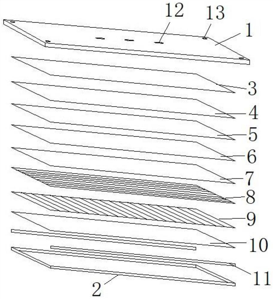
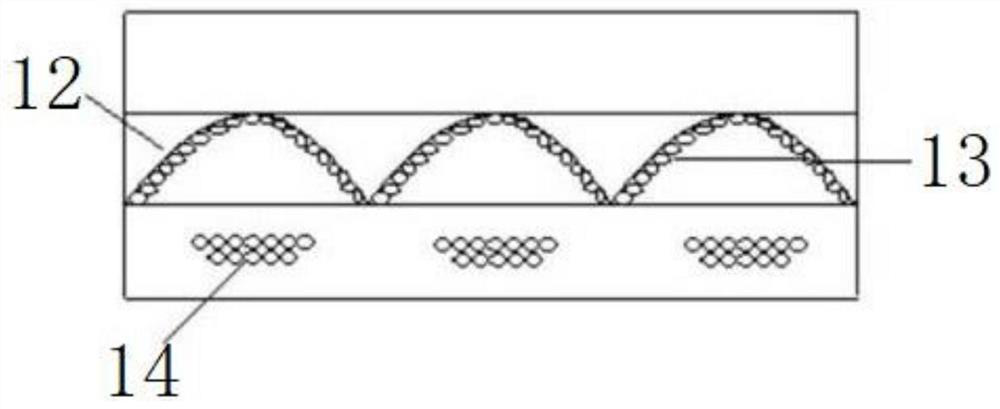
[0030] Such as Figure 1 to Figure 5 As shown, a LED lamp for classrooms includes a mounting board 1 and an LED lamp assembly. The LED lamp assembly includes a lamp frame 2, an opaque plate 3 arranged inside the lamp frame 2 and arranged in sequence, a reflective film 4, a guide The light plate 5, the diffusion film 6 and the prism plate 10, the side of the light guide plate 5 is provided with an LED light source 11 that emits light toward the light guide plate 5, the surface of the diffusion film 6 is provided with a glare control layer, and the glare control layer is provided with a hollow The light guide plate 5 is provided with a hollow layer, and the hollow layer is arranged with a reflective support mechanism for guiding the light emitted by the LED light source 11 to the light-emitting surface of the light guide plate 5 and supporting the upper and lower end surfaces of the hollow layer. Wherein, there are preferably multiple hollow holes, and the multiple hollow holes ...

Embodiment 2

[0042] Such as Image 6 As shown, the difference between this embodiment and Embodiment 1 is that the LED lamp assembly further includes a glare control layer disposed on the upper surface of the prism plate. The glare control layer is a coating layer, and the coating layer has high smoothness and good reflection effect, which can reduce the loss of light.

[0043] The LED light source 11 includes an FPC circuit board and lamp beads arranged in the length direction of the FPC circuit board.

[0044] Such as Figure 7 As shown, in order to protect the LED lamp assembly and avoid accidental contact with the outside world, causing accidental damage to the LED lamp assembly, a lampshade 15 can be arranged outside the LED lamp assembly, and the lampshade is installed on the mounting plate. The installation method can be clamped or through Fasten the screw to secure the connection.

Embodiment 3

[0046] The difference between this embodiment and Embodiment 2 is that the lamp beads are divided into red lamp beads, yellow lamp beads, blue lamp beads and white lamp beads; the LED lamp assembly also includes a control circuit unit, and the control circuit unit includes an LED drive module. The LED driver module is connected with each lamp bead, and controls each lamp bead individually; the control switch of the control circuit unit is set on the side wall of the classroom, and is used to control the opening and closing of the four lamp beads respectively. When in use, the lamp beads of corresponding colors can be turned on and off according to the needs of use.


PUM


Abstract

The LED lamp comprises a mounting plate and an LED lamp assembly. The LED lamp assembly comprises a lamp frame, a lightproof plate, a reflecting film, a light guide plate, a diffusion film and a prismatic crystal plate, wherein the lightproof plate, the reflecting film, the light guide plate, the diffusion film and the prismatic crystal plate are arranged on the inner side of the lamp frame in sequence, and an LED light source emitting light towards the light guide plate is arranged on the side face of the light guide plate; the glare control layer is provided with a hollow hole, a hollow layer is arranged in the light guide plate, and reflection supporting mechanisms which are used for guiding light emitted by the LED light source to the light outlet face of the light guide plate and canlimit and support the upper end face and the lower end face of the hollow layer are arranged in the hollow layer. Through arrangement of the glare control layer, illumination of the LED classroom lampis more uniform, and the anti-dazzling effect is better; the reflection support mechanism in the hollow layer of the light guide plate gives consideration to the power consumption of the light sourceand the uniform light generation effect.

Description

technical field [0001] The invention relates to the technical field of lighting, in particular to an LED lamp for classrooms. Background technique [0002] LED lamps have been widely used in the prior art and have become a common lighting device in people's daily life. For example, in the lighting of rooms, classrooms and other occasions, using LED ceiling lamps for lighting is a common lighting solution in the prior art. [0003] As a lighting appliance, classroom lights create a good classroom light environment for learning and make an important contribution to the formation of a good learning environment. However, at present, the bottom of most classroom lamps uses a grid plate to prevent the glare of the light. Because the distance and height of the grid plate are difficult to adjust to completely prevent the glare, the overall lighting effect of the classroom lamp is not good. Good, the visual effect is not good, and the thickness of the lamp that uses the grid plate t...

Claims


Application Information

Patent Timeline
Patent Type & Authority Applications(China)
IPC IPC(8): F21S8/00F21V5/00F21V13/00F21Y115/10
CPCF21S8/00F21V5/00F21V13/00F21Y2115/10
Inventor 刘承汐刘梅王东方
Owner 安徽省富鑫雅光电科技有限公司
Learn More