Method and system for detecting server cable, equipment and medium

A server and cable technology, which is applied in the field of detecting server cables, can solve the problems that the coding relationship cannot be changed flexibly, cannot be used, occupied, etc., and achieves the effects of rich IO resources, strong versatility, and flexible programming

Active Publication Date: 2021-01-29
INSPUR SUZHOU INTELLIGENT TECH CO LTD
View PDF1 Cites 6 Cited by
  • Summary
  • Abstract
  • Description
  • Claims
  • Application Information

AI Technical Summary

Problems solved by technology

[0005] The method of measuring the voltage value through the voltage-dividing resistor and using analog-to-digital conversion, when the number of cable channels is large, it will be necessary to calculate a variety of different voltage-dividing resistance values, which will not only occupy a large test fixture PCB (printed circuit Board) board area, and the accuracy of the analog-to-digital conversion ADC due to resistance resistance accuracy, power supply interference, etc., may easily cause misjudgment
[0006] The MCU is used to match the encoder / decoder, affected by the bit width of the encoder / decoder, it will no longer be applicable when the number of cable channels is large, and the encoding relationship is fixed and cannot be changed flexibly. The sequence channel only uses two constant level logics of 0 / 1. In the case of a large number of cable channels and a changeable line sequence relationship, the encoder / decoder mechanism will no longer be applicable.
[0007] In particular, slimline (thin cable) x4 has 38 pins, and slimline x8 has 74 pins. In this case, the above method obviously cannot be used

Method used


Image

  • Method and system for detecting server cable, equipment and medium
  • Method and system for detecting server cable, equipment and medium
  • Method and system for detecting server cable, equipment and medium

Examples


Embodiment Construction

[0026] In order to make the object, technical solution and advantages of the present invention clearer, the embodiments of the present invention will be further described in detail below in conjunction with specific embodiments and with reference to the accompanying drawings.

[0027] It should be noted that all expressions using "first" and "second" in the embodiments of the present invention are to distinguish two entities with the same name but different parameters or parameters that are not the same, see "first" and "second" It is only for the convenience of expression, and should not be construed as a limitation on the embodiments of the present invention, which will not be described one by one in the subsequent embodiments.

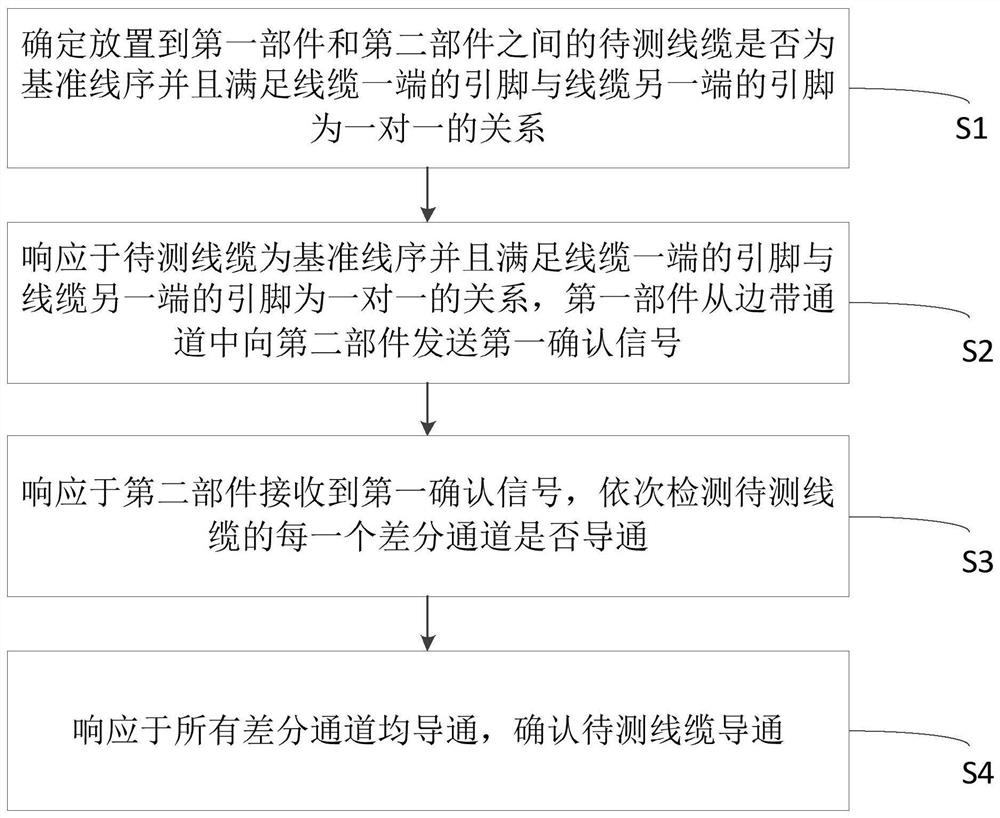
[0028] Based on the above purpose, the first aspect of the embodiments of the present invention provides an embodiment of a method for detecting server cables. figure 1 What is shown is a schematic diagram of an embodiment of the method for detectin...


PUM


Abstract

The invention discloses a method and a system for detecting a server cable, equipment and a storage medium. The method comprises the steps that whether a to-be-detected cable placed between a first component and a second component is a datum line sequence or not is determined, and the one-to-one relationship between a pin at one end of the cable and a pin at the other end of the cable is met; thefirst component sends a first confirmation signal to the second component from the sideband channel in response to the fact that the to-be-detected cable is a reference line sequence and the one-to-one relationship between the pin at one end of the cable and the pin at the other end of the cable is met; responding to the first confirmation signal received by the second component, and sequentiallydetecting whether each differential channel of the to-be-detected cable is conducted or not; and responding to conduction of all the differential channels, and determining conduction of the to-be-tested cable. According to the invention, the cable connectivity detection mechanisms of different modes are designed according to the requirements of different applications, the universality is high, andthe common high-speed cable test development and detection process is greatly simplified.

Description

technical field [0001] The present invention relates to the field of cable detection, more specifically, to a method, system, computer equipment and readable medium for detecting server cables. Background technique [0002] With the continuous development of Internet artificial intelligence technology, the traditional server architecture has been difficult to adapt to the ever-changing data processing and data storage requirements. The increasing demand continues to catalyze and derive various forms of servers that integrate heterogeneous computing. The new heterogeneous computing servers have been improved to varying degrees: on the one hand, while complying with the size requirements of standard racks, the height of the server chassis has been continuously increased, and a larger internal space has been designed to add more computing units and heterogeneous acceleration. module, FPGA accelerated network card, GPU processor, etc.; on the other hand, the traditional managem...

Claims


Application Information

Patent Timeline
Patent Type & Authority Applications(China)
IPC IPC(8): G06F11/22
CPCG06F11/221G06F11/2273Y02D10/00
Inventor 王树明
Owner INSPUR SUZHOU INTELLIGENT TECH CO LTD
Why Eureka
Try Eureka