Crack monitoring management system and monitoring management method

A technology for monitoring management and cracks, applied in the direction of measuring devices, image data processing, instruments, etc., can solve the problems of untimely discovery, data reading errors, and the inconvenient method of manual observation of cracks, etc., to achieve monitoring and calculation data Accurate, avoid data loss, implement convenient and fast effects

Active Publication Date: 2021-01-29
上海同禾工程科技股份有限公司
View PDF5 Cites 3 Cited by
  • Summary
  • Abstract
  • Description
  • Claims
  • Application Information

AI Technical Summary

Problems solved by technology

[0004] 1) Monitoring personnel are required to stay at the site for a long time to observe whether there are cracks in the structure of the site structure, so as to install the rod-type crack meter or rope-type crack meter in time after the cracks appear. The method of manually observing the cracks is not convenient;
[0005] 2) It is necessary to manually read the data of the rod-type crack meter or the pull-rope crack meter manually. The manual reading method often causes errors in data reading, and when the cracks crack to a large extent, they cannot be found in time, and cause safety hazard
[0006] At present, there are also wireless rod-type crack gauges or wireless pull-cord crack gauges on the market, which can upload crack cracking data to the cloud in real time for monitoring personnel to read. However, due to rain and snow, the pull rope will be forced to extend. As a result, the data uploaded to the cloud is wrong, and the monitoring personnel cannot accurately identify whether there is a real risk, resulting in potential safety hazards

Method used


Image

  • Crack monitoring management system and monitoring management method
  • Crack monitoring management system and monitoring management method
  • Crack monitoring management system and monitoring management method

Examples


Embodiment Construction

[0038] The following is attached figure 1 To attach image 3 , to further illustrate the present invention through specific embodiments.

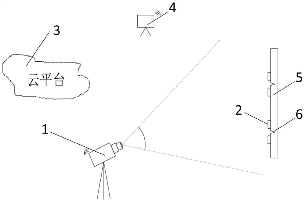
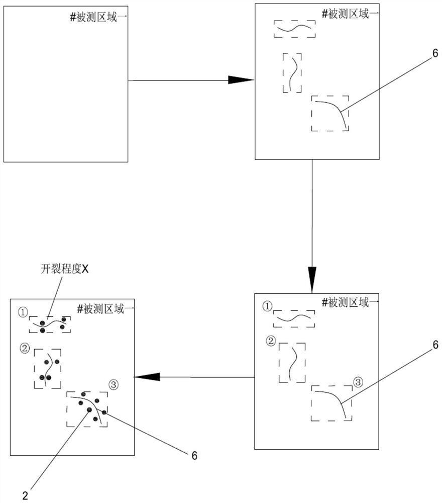
[0039] Please refer to figure 1 As shown, the present invention discloses a crack monitoring and management system for monitoring and managing each crack 6 on each measured area 5 of the measured object.

[0040] The crack monitoring and management system includes an on-site monitoring and calculation system, a cloud platform computing management system 3 and a client viewing system 4.

[0041] The on-site monitoring and solving system includes a smart camera 1 and a characteristic target 2 . The object to be measured is provided with a plurality of measured areas 5, and a smart camera 1 is set at a position corresponding to each measured area 5, and each smart camera 1 observes the corresponding measured area 5 within the field of view. The way of independent monitoring combination is to monitor the whole of the measured object. The c...


PUM


Abstract

The invention discloses a crack monitoring and management system, which comprises a field monitoring and resolving system, a cloud platform computing and management system and a client viewing system;the field monitoring resolving system comprises an intelligent camera and characteristic targets; the characteristic targets are arranged on the two sides of crack, and the intelligent camera recognizes and observes the characteristic targets arranged on the two sides of crack, monitors whether the characteristic targets arranged on the two sides of the crack generate relative displacement or not, resolves relative displacement data x of the characteristic targets arranged on the two sides of the crack, and uploads the relative displacement data x to a cloud platform computing management system; in an initial state, a monitoring person measures the initial cracking distance x1 of a crack and inputs the monitored initial cracking distance x1 of the crack to the cloud platform computing management system through the client viewing system; and in a real-time monitoring state, after the cloud platform computing management system receives the relative displacement data x, input by the intelligent camera, of the characteristic targets on the two sides of the corresponding crack, the cracking degree X = x1 + delta x of the crack is calculated in real time.

Description

technical field [0001] The invention relates to the technical field of structure crack monitoring and management, in particular to a crack monitoring and management system and a monitoring and management method based on machine vision technology. Background technique [0002] After different structures (such as bridges, tunnels, etc.) are put into use, in addition to bearing various natural loads, they will also inevitably bear driving dynamic loads, overloads or impacts, etc., which will inevitably cause structural mechanical or structural performance. Changes, this internal change will be manifested in the form of cracks. In order to understand the safety status of the structure, it is necessary to conduct long-term safety monitoring of the cracks that appear on it to prevent accidents such as the collapse of the structure. [0003] The traditional crack monitoring method installs a rod-type crack meter or a rope-type crack meter at the crack. When the crack is opened, the...

Claims


Application Information

Patent Timeline
Patent Type & Authority Applications(China)
IPC IPC(8): G06T7/00G01N21/84G01B11/14
CPCG06T7/0008G01N21/84G01B11/14G06T2207/10004G06T2207/30232
Inventor 宋爽徐辉姚鸿梁
Owner 上海同禾工程科技股份有限公司
Why Eureka
Try Eureka