Wire loosening device for communication cable stripping machine

A communication cable and stripping machine technology, which is applied in the direction of cable installation device, cable installation, dismantling/armored cable equipment, etc., can solve the problem that the insulation skin cable core is difficult to peel off, so as to promote separation, promote dislocation separation, The effect of improving efficiency

Inactive Publication Date: 2021-01-29
王成艳
View PDF0 Cites 1 Cited by
  • Summary
  • Abstract
  • Description
  • Claims
  • Application Information

AI Technical Summary

Problems solved by technology

[0005] The purpose of the present invention is to solve the problem that the insulation skin is easy to fit closely with the cable core and is difficult to peel

Method used


Image

  • Wire loosening device for communication cable stripping machine
  • Wire loosening device for communication cable stripping machine
  • Wire loosening device for communication cable stripping machine

Examples


Embodiment 1

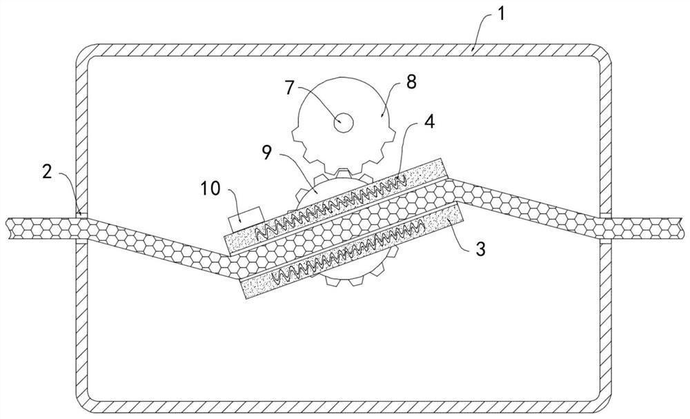
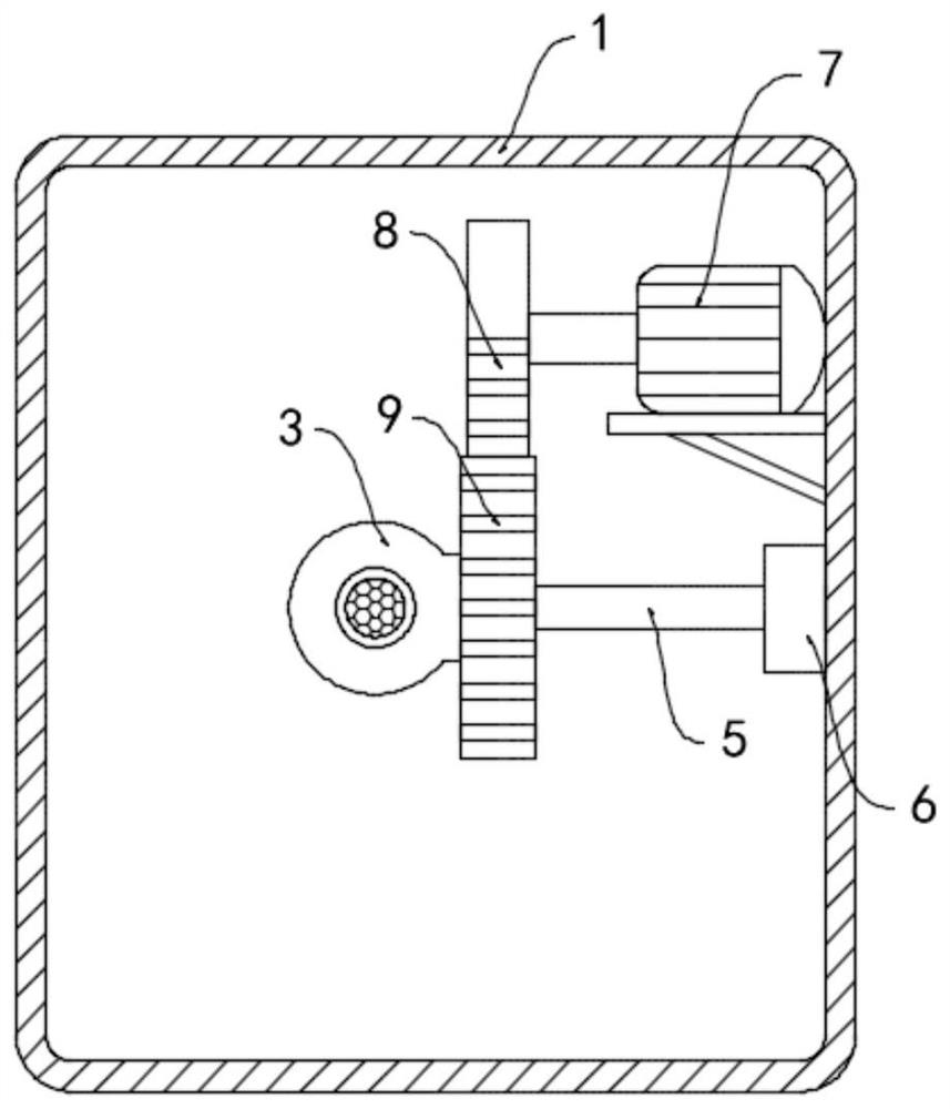
[0021] Such as Figure 1-2 As shown, a wire loosening device for a communication cable stripping machine includes a housing 1, the side walls on both sides of the housing 1 are provided with threading holes 2, the housing 1 is provided with a sleeve 3, and the sleeve 3 is embedded A heating resistance wire 4 is provided, and the heating resistance wire 4 is electrically connected to an external power supply. A temperature alarm 10 is installed on the casing 3. The temperature alarm 10 can monitor the temperature at the casing 3 in real time to prevent the insulation skin from being overheated. melted, and the temperature of the control sleeve 3 is within a suitable temperature range.

[0022] The casing 3 is rotationally connected with the inner side wall of the housing 1 through the rotating shaft 5, the rotating shaft 5 is provided with a coil spring 6, the inner ring of the coil spring 6 is fixed to the rotating shaft 5, and the outer ring is fixed to the inner side wall of...

Embodiment 2

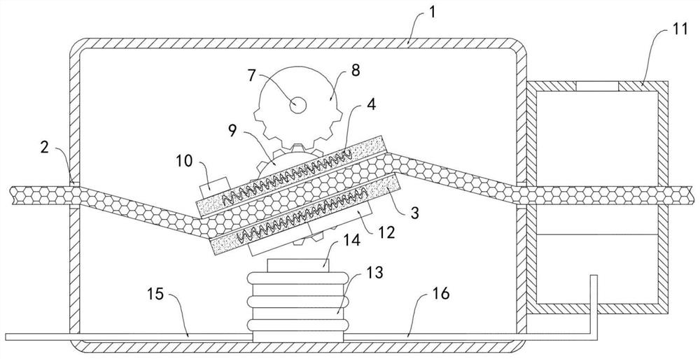
[0026] Such as image 3 As shown, the difference between this embodiment and Embodiment 1 is that a cooling air box 11 is fixedly connected to the side wall of the housing 1, and a through hole matching the threading hole 2 is provided on the side wall of the cooling air box 11. 3 is fixedly connected to the side wall of the permanent magnet strip 12 extending along its axial direction, the magnetic poles at both ends of the permanent magnet strip 12 are opposite, and the inner bottom surface of the housing 1 is fixedly connected to a vertically arranged airbag 13, and the upper end of the airbag 13 is fixedly connected to There is a magnet block 14 matched with the permanent magnet strip 12, a one-way air intake pipe 15 and a one-way exhaust pipe 16 are fixedly communicated with the side wall of the air bag 13, and the air intake end of the one-way air intake pipe 15 extends to the outside of the housing 1, The air outlet end of the one-way exhaust pipe 16 extends into the co...


PUM


Abstract

The invention belongs to the technical field of communication cables, and particularly relates to a wire loosening device for a communication cable stripping machine, which comprises a shell, threading holes are formed in the side walls of the two sides of the shell, a sleeve is arranged in the shell, a heating resistance wire is embedded in the sleeve, and the heating resistance wire is electrically connected with an external power supply. The sleeve is rotatably connected with the inner side wall of the shell through a rotating shaft, the rotating shaft is sleeved with a coil spring, the inner ring of the coil spring is fixed to the rotating shaft, the outer ring of the coil spring is fixed to the inner side wall of the shell, a driving motor is installed on the inner side wall of the shell, and a sector gear is coaxially and fixedly installed on an output shaft of the driving motor. The communication cable is heated, the principle that the thermal expansion coefficients of the insulation skin and the cable core are different is utilized, the insulation skin and the cable core are separated, the communication cable is bent and twisted in a reciprocating mode through rotation of the sleeve, separation of the insulation skin and the cable core is further promoted, and peeling processing is facilitated.

Description

technical field [0001] The invention belongs to the technical field of communication cables, in particular to a wire loosening device for a communication cable stripping machine. Background technique [0002] Communication cables are cables that transmit telephones, telegraphs, fax files, TV and radio programs, data and other electrical signals. Communication cables are widely used in people's lives and production processes. The recycling of old cables is of great significance. Therefore It is necessary to strip the insulating surface layer of the surface by a communication cable stripping machine. [0003] Most of the traditional communication cable stripping machines directly cut the skin of the communication cable with a cutting blade for peeling treatment. However, due to the long-term use of the old communication cable, the insulation skin and the cable core are closely attached or even adhered together. Difficult cutting and incomplete peeling will occur, reducing wor...

Claims


Application Information

Patent Timeline
IPC IPC(8): H01B15/00H02G1/12
CPCH01B15/00H01B15/001H01B15/003H02G1/12H02G1/1275Y02W30/82
Inventor 王成艳徐勇
Owner 王成艳
Why Eureka
Try Eureka