Ion implantation method, device and equipment

An ion implantation and equipment technology, which is applied to discharge tubes, electrical components, circuits, etc., can solve problems such as uneven ion doping concentration, and achieve the effects of improving uniformity and shortening ion implantation time.

Active Publication Date: 2021-01-29
泉芯集成电路制造(济南)有限公司
View PDF12 Cites 0 Cited by
  • Summary
  • Abstract
  • Description
  • Claims
  • Application Information

AI Technical Summary

Problems solved by technology

Inhomogeneous ion doping concentration obtained by ion implantation of the sample using a ribbon ion beam

Method used


Image

  • Ion implantation method, device and equipment
  • Ion implantation method, device and equipment
  • Ion implantation method, device and equipment

Examples


Embodiment Construction

[0032] The present invention will be further described in detail below in conjunction with the accompanying drawings and embodiments. It should be understood that the specific embodiments described here are only used to explain the present invention, but not to limit the present invention. In addition, it should be noted that, for the convenience of description, only some structures related to the present invention are shown in the drawings but not all structures.

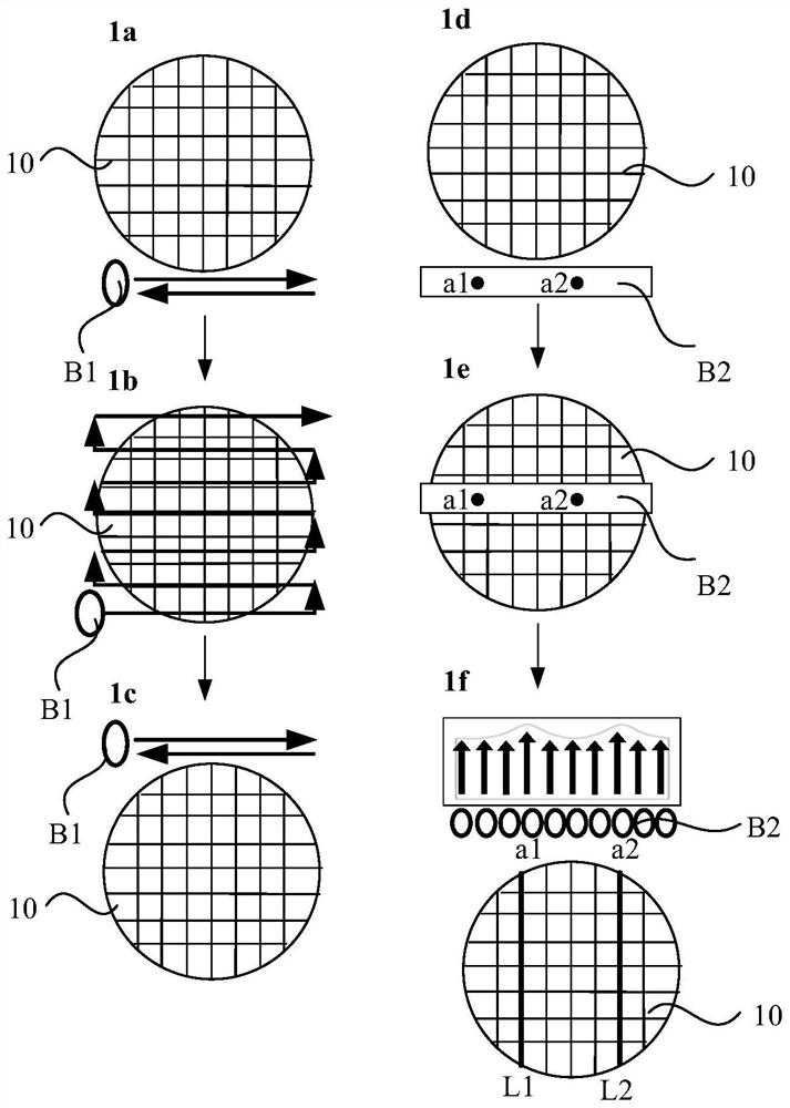
[0033] As mentioned in the above background technology, the current ion implantation method usually moves the sample in a straight line relative to the point-shaped ion beam or ribbon-shaped ion beam, and the point-shaped ion beam or ribbon-shaped ion beam performs ion implantation on the sample. , and its linear motion direction is perpendicular to the extension direction of the point-like ion beam or the ribbon-like ion beam. The time for ion implantation on the sample with spot ion beam is too long. The ion do...


PUM


Abstract

The invention discloses an ion implantation method, device and equipment. The ion implantation method comprises the following steps: providing a strip-shaped ion beam current; and when a sample rotationally moves from the first end of the strip-shaped ion beam current to the second end of the strip-shaped ion beam current, and controlling the strip-shaped ion beam current to perform ion implantation on the sample, wherein the direction from the first end of the strip-shaped ion beam current to the second end is the extension direction of the strip-shaped ion beam current. According to the technical scheme provided by the embodiment of the invention, the uniformity of ion doping on the surface of the sample wafer is improved on the basis of shortening the ion implantation time of the samplewafer.

Description

technical field [0001] Embodiments of the present invention relate to the technical field of semiconductors, and in particular to an ion implantation method, device and equipment. Background technique [0002] In the manufacturing process of semiconductor integrated circuits, it is a common process to dope samples by ion implantation. [0003] The current ion implantation method usually moves the sample in a straight line relative to the point-shaped ion beam or ribbon-shaped ion beam. The extension direction of the shaped ion beam or the ribbon ion beam. Ion implantation of the sample with a spot ion beam takes too long. The ion doping concentration obtained by using the ribbon ion beam to implant the sample is not uniform. [0004] Therefore, there is an urgent need for an ion implantation method with short ion implantation time and uniform doping concentration. Contents of the invention [0005] In view of this, the embodiments of the present invention provide an io...

Claims


Application Information

Patent Timeline
Patent Type & Authority Applications(China)
IPC IPC(8): H01L21/265H01J37/317
CPCH01L21/265H01J37/3171
Inventor 杨学人
Owner 泉芯集成电路制造(济南)有限公司
Why Eureka
Try Eureka