
Detachable automatic feeding device for lead screw machining

An automatic feeding and dismantling technology, applied in metal processing, metal processing equipment, manufacturing tools, etc., can solve the problems of clutter, inconvenient process, unable to automatically push the screw, and achieve the effect of preventing falling and storing firmly.

Inactive Publication Date: 2021-02-02
东莞市隆润机械设计有限公司
View PDF0 Cites 0 Cited by
  • Summary
  • Abstract
  • Description
  • Claims
  • Application Information

AI Technical Summary

Problems solved by technology

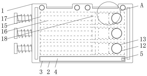
[0004] The purpose of the present invention is to provide a detachable automatic feeding device for screw mandrel processing, to solve the problem that the existing feeding device proposed in the above background technology has no good fitting structure at its end, resulting in its thread The raw material body of the rod is poorly organized and messy during storage, which is not conducive to processing operations such as discharging. At the same time, its end cannot properly push the screw rod automatically, resulting in inconvenient feeding process. Not concise enough to use

Method used


Image

  • Detachable automatic feeding device for lead screw machining
  • Detachable automatic feeding device for lead screw machining
  • Detachable automatic feeding device for lead screw machining

Examples


Embodiment Construction

[0026] The following will clearly and completely describe the technical solutions in the embodiments of the present invention with reference to the accompanying drawings in the embodiments of the present invention. Obviously, the described embodiments are only some, not all, embodiments of the present invention.

[0027] In the description of the present invention, unless otherwise stated, the meaning of "plurality" is two or more; the terms "upper", "lower", "left", "right", "inner", "outer" , "front end", "rear end", "head", "tail", etc. indicate the orientation or positional relationship based on the orientation or positional relationship shown in the drawings, and are only for the convenience of describing the present invention and simplifying the description, rather than Indicates or implies that the device or element referred to must have a particular orientation, be constructed and operate in a particular orientation, and therefore should not be construed as limiting the...


PUM


Abstract

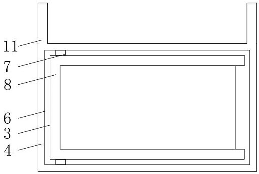
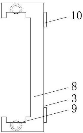
The invention relates to a detachable automatic feeding device for lead screw machining. The detachable automatic feeding device for lead screw machining comprises a base and round openings, a seat opening is formed in the front wall of the bottom end of the base, an inner storage mechanism is installed at the inner side end of the seat opening, the round openings are formed in the right end of the base, inner sealing plates are installed at the inner side ends of the round openings, plate sliding adjusting grooves are formed in the outer sides of the left ends of the inner sealing plates, andan inner cavity is formed in the middle of the base. The detachable automatic feeding device for lead screw machining has the beneficial effects that an embedded shaft is used for rotating an inner lapping frame plate, then the inclination degree of the inner lapping frame plate is conveniently changed, operation of taking up and paying off lead screw raw materials is better carried out, meanwhile, a plate buckle at the end of the inner lapping frame plate can be clamped with a storage frame, butt joint and combination between the inner lapping frame plate and the storage frame are convenient, a concave arc-shaped opening in the side end of the inner lapping frame plate can facilitate butt joint of two ends of the lead screw raw materials, so that the lead screw raw materials are firmer during storage, and the situations of falling and the like are prevented.

Description

technical field [0001] The invention relates to the technical field of screw mandrel processing, in particular to a detachable automatic feeding device for screw mandrel processing. Background technique [0002] The ball screw is an ideal product for converting rotary motion into linear motion, or converting linear motion into rotary motion. It generally needs to use an automatic feeding device during processing to assist it in feeding processing. [0003] Due to the fact that the end of the existing feeding device is not designed with a good bonding structure, the raw material body of the screw rod is poorly organized and messy during storage, which is not conducive to processing operations such as discharging, and at the same time, the end of the device cannot It is very good to reasonably and automatically push the screw rod, which makes the process of feeding it not convenient enough and not simple enough to use. Contents of the invention [0004] The purpose of the p...

Claims


Application Information

Patent Timeline
Patent Type & Authority Applications(China)
IPC IPC(8): B23P19/06B23P19/00B65G47/82B65G47/74
CPCB23P19/001B23P19/06B65G47/74B65G47/82
Inventor 张建云冯辉宗方良达
Owner 东莞市隆润机械设计有限公司
Learn More