
Whole tube assembly tool for vacuum arc-extinguishing chamber

A vacuum interrupter and assembly tooling technology, applied in the direction of electrical components, electric switches, circuits, etc., can solve the problems of low assembly accuracy and low efficiency, and achieve the effect of ensuring locking accuracy and wide application range

Active Publication Date: 2021-06-08
PINGGAO GRP +2
View PDF20 Cites 0 Cited by
  • Summary
  • Abstract
  • Description
  • Claims
  • Application Information

AI Technical Summary

Problems solved by technology

[0004] The purpose of the present invention is to provide an assembly tooling for the whole tube of vacuum interrupter to solve the problem of low assembly accuracy caused by manually centering and assembling adjacent ceramic shells in the prior art for high-voltage arc extinguishing chambers with multiple ceramic shells. inefficient technical issues

Method used


Image

  • Whole tube assembly tool for vacuum arc-extinguishing chamber
  • Whole tube assembly tool for vacuum arc-extinguishing chamber
  • Whole tube assembly tool for vacuum arc-extinguishing chamber

Examples


Embodiment 1

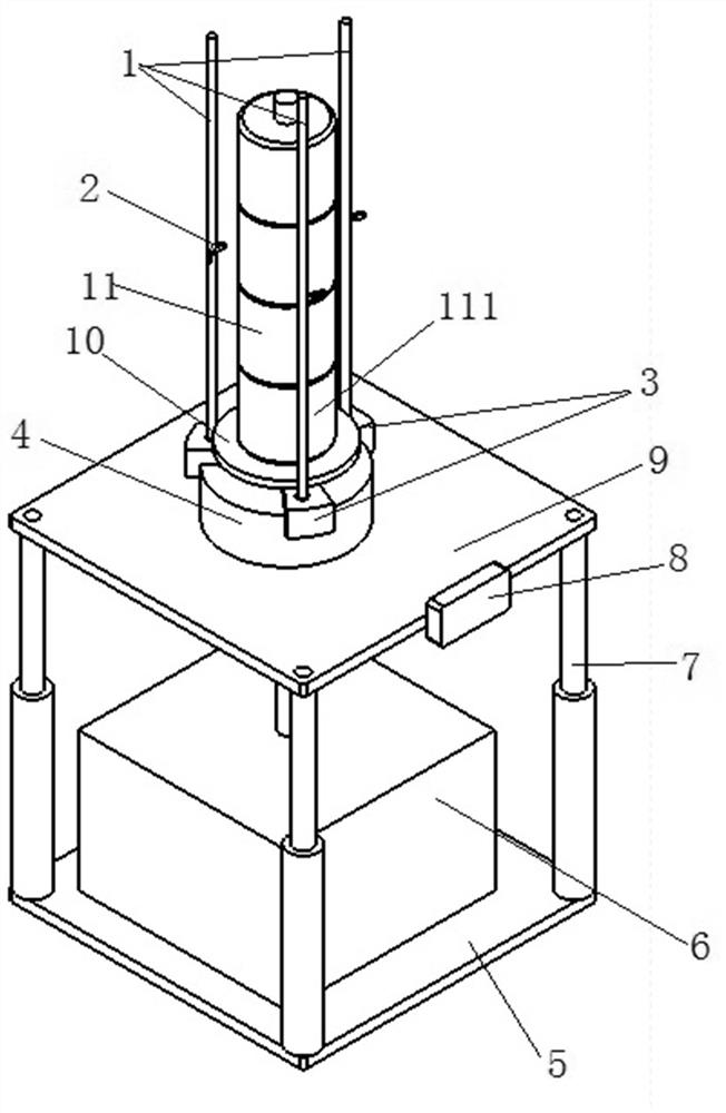
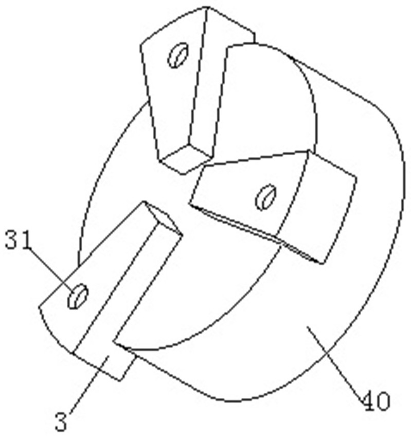
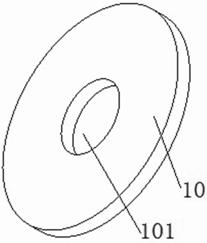
[0041] Such as Figure 1 to Figure 4As shown, the assembly tooling for the entire tube of the vacuum interrupter in this embodiment includes a lifting platform, which can move up and down vertically, and a chuck 4 is fixed on the lifting platform, and an assembly plate 10 is placed on the chuck 4. , used to support and place parts to assemble the vacuum interrupter 11, three centering shafts 1 are fixed on the chuck 4, the three centering shafts 1 extend vertically in parallel, and the three centering shafts 1 extend along the lifting platform The circumferential intervals are evenly distributed to form a positioning cylindrical surface, that is, on the same circumference, each centering shaft 1 is equipped with a centering piece 2 that is movable along a vertical guide, and the inner part of the centering piece 2 deviates from the centering shaft. There is a centering pressure head at the end. When assembling, first use the bottom porcelain shell 111 of the vacuum interrupter...

specific Embodiment 2

[0054] It differs from Embodiment 1 mainly in that: in Embodiment 1, three claws are arranged on the chuck. In this embodiment, four claws can be set on the chuck, and the four claws are evenly spaced along the circumferential direction of the chuck. Each claw is fixedly equipped with a centering shaft, and each centering shaft guides and moves respectively. Assembled with centering piece.

specific Embodiment 3

[0056] It differs from Embodiment 1 mainly in that: in Embodiment 1, the elastic member is a compression spring. In this embodiment, the elastic member can also be a tension spring. At this time, the sliding member can be designed as a chute, and the centering pressure head has a sliding section that fits and guides the chute. The radial dimension of the sliding section is relatively thick, so as to A stop step is formed, the above-mentioned extension spring is set on the centering pressure head, one end is hooked and connected with the hook structure provided on the corresponding end of the sliding section, and the other end is hooked and connected with the hook head at the corresponding end of the chute.


PUM


Abstract

The invention relates to a whole tube assembly tool for a vacuum arc-extinguishing chamber. The tool comprises: a lifting platform which is used for supporting and placing parts so as to assemble the vacuum arc-extinguishing chamber; and centering shafts fixedly arranged on the lifting table, wherein at least three centering shafts are uniformly distributed at intervals in the circumferential direction to form a positioning cylindrical surface. A centering piece is assembled on each centering shaft in the vertical direction in a guiding and moving mode, each centering piece extends in the radial direction of the positioning cylindrical face and is perpendicular to the corresponding centering shaft, a centering jacking head is arranged at the end, away from the corresponding centering shaft, of each centering piece, and when the centering pieces move in the vertical direction, each centering top pressure head is used for being in top pressure fit with the peripheral surface of each stage of porcelain shell of the vacuum arc-extinguishing chamber so as to ensure that each stage of porcelain shell which is placed layer by layer is coaxially arranged. During use, the positions of the centering pieces are lifted step by step on the centering shaft by utilizing the mutual correction of a bottom-layer ceramic shell and the three centering pieces, and the positions of the sequentially stacked ceramic shells are centered and calibrated, so that the coaxiality of all the ceramic shells can be effectively ensured, and the assembly precision of the whole arc extinguish chamber is conveniently ensured.

Description

technical field [0001] The invention belongs to the field of electric switch manufacturing equipment, and in particular relates to a complete tube assembly tool for a vacuum interrupter. Background technique [0002] The production process of the existing low-voltage vacuum interrupter is very mature. All major domestic manufacturers of interrupter have mature assembly processes for the whole tube, such as the assembly and calibration of the vacuum interrupter disclosed in the Chinese invention patent with the authorized announcement number CN108962648B Fixtures, better overall pipe assembly fixtures can greatly improve the production efficiency of workers and ensure the pass rate of finished products. [0003] For vacuum interrupters with a voltage level of 126kV and above, a multi-porcelain shell structure is generally adopted. When assembling, the bottom porcelain shell is placed first, and the corresponding components are fixed and installed based on the bottom porcelain...

Claims


Application Information

Patent Timeline
IPC IPC(8): H01H11/00
CPCH01H11/00H01H2011/0075
Inventor 李锟李小钊刘畅薛从军刘世柏赵芳帅齐大翠亓春伟海竣超尹婷王茜姚锋娟谷凤娟刘心悦
Owner PINGGAO GRP
Learn More