
Centrifugal fire pump

A centrifugal and water pump technology, which is applied in the direction of non-variable pumps, non-volume pumps, pumps, etc., can solve the problem of affecting the restart of the centrifugal fire-fighting water pump, the poor protection effect of the centrifugal fire-fighting water pump, and the damage of the centrifugal fire-fighting water pump and other problems, to achieve the effect of being easy to restart and use, improving the protection effect, and realizing the protection effect

Active Publication Date: 2021-08-27
河北森之盾消防科技有限责任公司
View PDF10 Cites 0 Cited by
  • Summary
  • Abstract
  • Description
  • Claims
  • Application Information

AI Technical Summary

Problems solved by technology

[0004] However, during the installation and fixing process of the above-mentioned central centrifugal fire pump, it is necessary to preset the installation structure that matches the mounting lugs on the mounting base, which is limited by the installation position and has poor practicability, and when the fire spreads to the centrifugal fire pump Once the location where the centrifugal fire pump is installed catches fire, it is very easy to cause damage to the centrifugal fire pump, and the self-protection effect of the centrifugal fire pump is poor. When it is not started for a long time, the water in the sealed chamber will be lost, which will affect the re-starting of the centrifugal fire pump

Method used


Image

  • Centrifugal fire pump
  • Centrifugal fire pump
  • Centrifugal fire pump

Examples


Embodiment

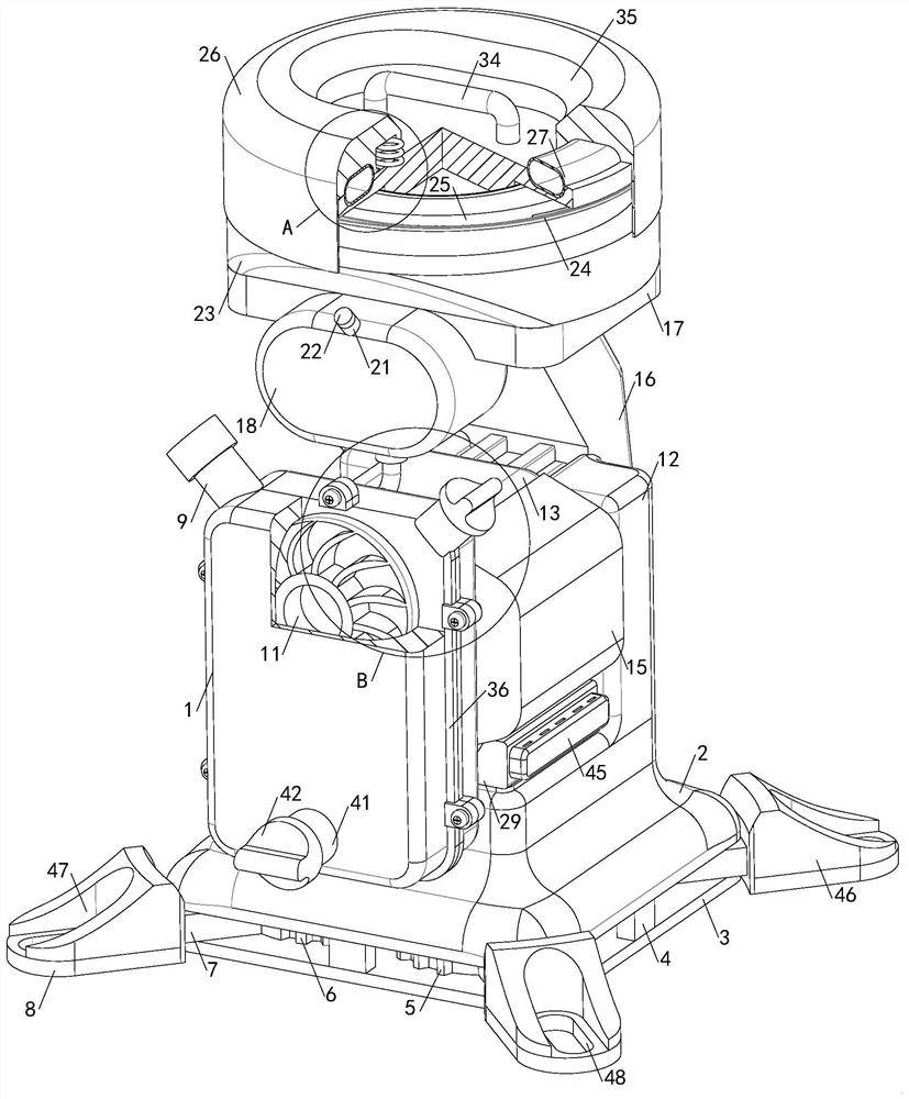
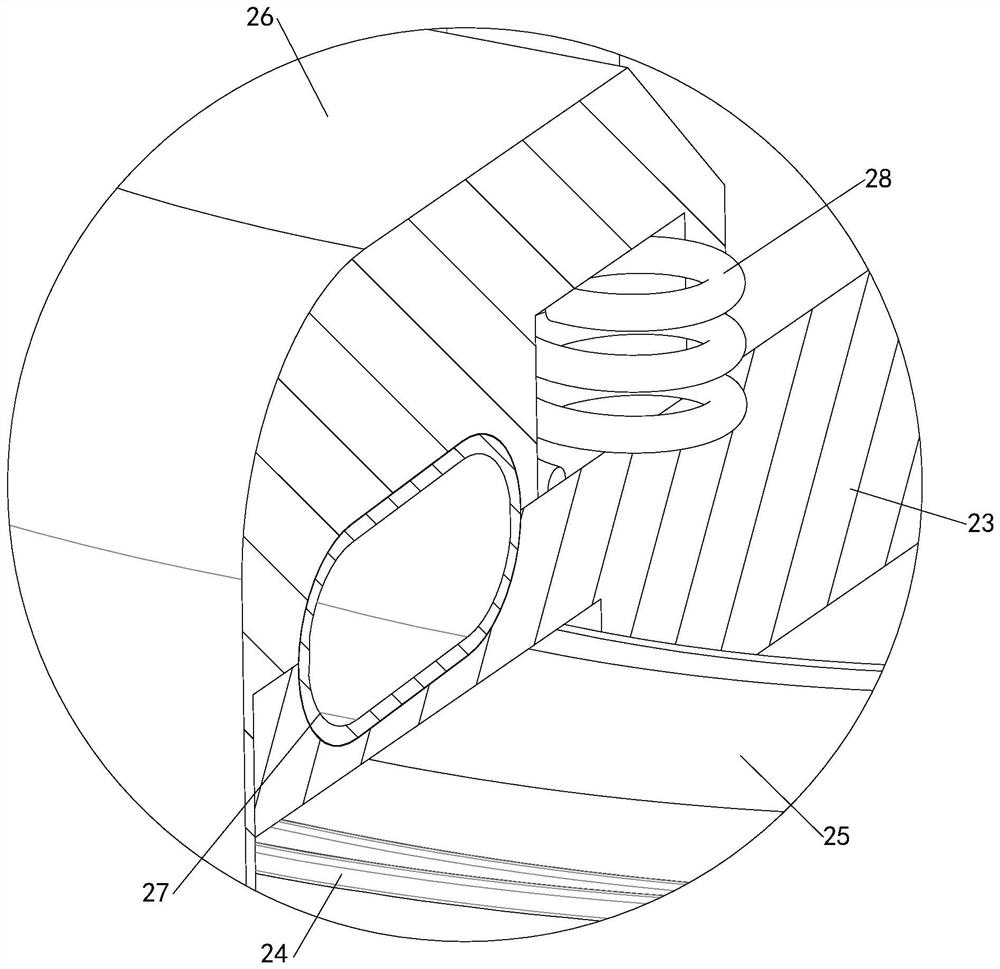
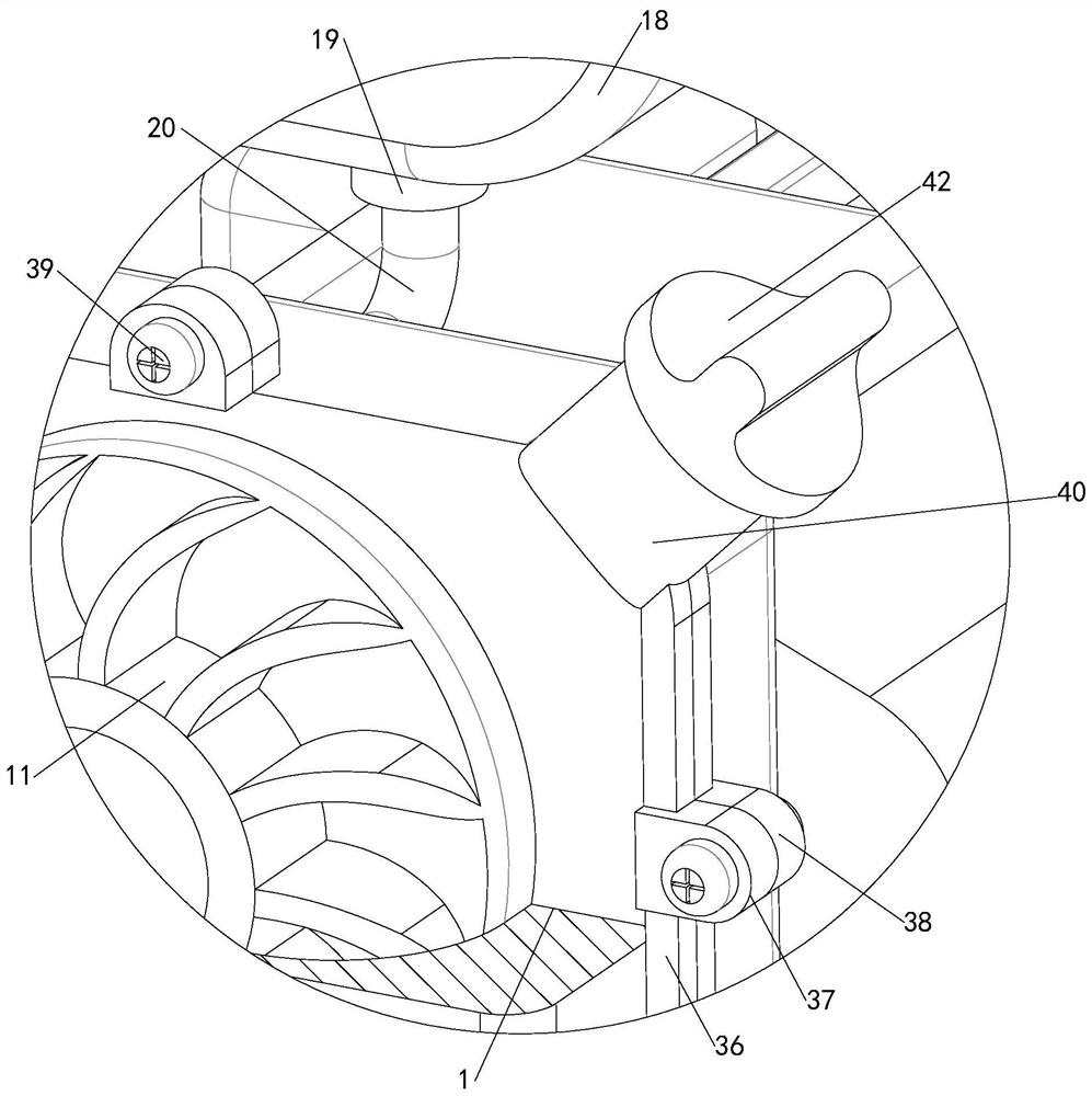
[0034] see Figure 1-8, a centrifugal fire pump, including a sealed chamber 1, and also includes an underframe 2 and a bottom plate 3, the underframe 2 and the bottom plate 3 are fixedly connected by a plurality of connecting blocks 4, and the bottom frame 2 and the bottom plate 3 are rotatably connected with Two main gears 5 and two sub-gears 6, two main gears 5 and two sub-gears 6 are arranged at intervals, adjacent main gears 5 and sub-gears 6 mesh with each other, and four mounting ears 8 can move in coordination, thereby It is convenient for the synchronous adjustment of the four mounting ears 8, and the practicability is better. Both the female gear 5 and the child gear 6 are fixedly connected with the connecting bar 7, and the end of the connecting bar 7 far away from the bottom frame 2 is fixedly connected with the mounting ear 8, so that During the installation process with the outside world, the position of the mounting ear 8 relative to the chassis 2 can be adjusted...


PUM


Abstract

The invention relates to the technical field of fire pumps, in particular to a centrifugal fire pump. The centrifugal fire pump comprises a sealing bin, a bottom frame and a bottom plate, the bottom frame is connected with the bottom plate, two mother gears and two son gears are connected between the bottom frame and the bottom plate, mounting lugs are connected to the mother gears and the son gears through connecting strips, and the sealing bin is mounted below the bottom frame. The sealing bin communicates with an input pipe connector and an inlet pipe connector, an efficient water wheel is mounted in the sealing bin, a fuel tank and an internal combustion engine are mounted on the bottom frame, and the fuel tank communicates with the internal combustion engine. An oil filling pipe communicates with the fuel tank, a fire extinguisher is mounted on the bottom frame, the bottom frame is connected with a mounting plate through an auxiliary frame, a standby water cylinder, an auxiliary electronic system and a fire insulation device are mounted on the mounting plate, an electromagnetic valve is mounted at the bottom end of the standby water cylinder in a communicating mode, and the electromagnetic valve communicates with the sealing bin through a bent pipe. The centrifugal fire pump can better adapt to various mounting environments, the practicability is good, self-protection can be achieved, the damage probability is reduced, and water can be automatically supplemented into the sealing bin.

Description

technical field [0001] The invention relates to the technical field of fire-fighting water pumps, in particular to a centrifugal fire-fighting water pump. Background technique [0002] As we all know, the centrifugal fire pump is a special pump installed on fire trucks, fixed fire extinguishing systems or other fire fighting facilities to transport liquid fire extinguishing agents such as water or foam solutions. It has the characteristics of full sealing, no leakage and corrosion resistance. It is an important core soul unit in the fire protection system. It is widely used in modern urban fire protection construction and plays an important role in the safety of people's lives and property. [0003] Existing centrifugal fire pumps generally include a pump body, the pump body includes a mounting base and a motor, the mounting base is fixedly connected with mounting ears, the mounting ears are provided with strip holes, the pump body is equipped with a sealing chamber, and the...

Claims


Application Information

Patent Timeline
IPC IPC(8): F04D1/00F04D29/62F04D29/58F04D29/42F04D13/02F02B63/06F02B77/00A62C31/00
CPCF04D1/00F04D29/628F04D29/588F04D29/426F04D13/02F02B63/06F02B77/00A62C31/00A62C99/0018Y02A20/00
Inventor 石刚
Owner 河北森之盾消防科技有限责任公司
Learn More