
Concrete well lid pouring mold and pouring method thereof

A technology for pouring molds and concrete, applied in the field of pouring molds for concrete manhole covers, can solve problems such as difficulty in achieving fair-faced concrete effects, easy contamination of the concrete surface, and manhole covers are not easy to demould, etc. Effect

Active Publication Date: 2021-02-02
广州市卓爵建筑工程有限公司
View PDF7 Cites 7 Cited by
  • Summary
  • Abstract
  • Description
  • Claims
  • Application Information

AI Technical Summary

Problems solved by technology

[0003] At present, there are many cement circular manhole covers on the roads in urban areas. The cement manhole covers are strong and firm; It is also easy to pollute the surface of the concrete, and it is difficult to achieve the effect of fair-faced concrete, and the mold is easy to bond to the concrete when it is demoulded, and it needs to be cleaned manually later, resulting in low work efficiency

Method used


Image

  • Concrete well lid pouring mold and pouring method thereof
  • Concrete well lid pouring mold and pouring method thereof
  • Concrete well lid pouring mold and pouring method thereof

Examples


Embodiment 1

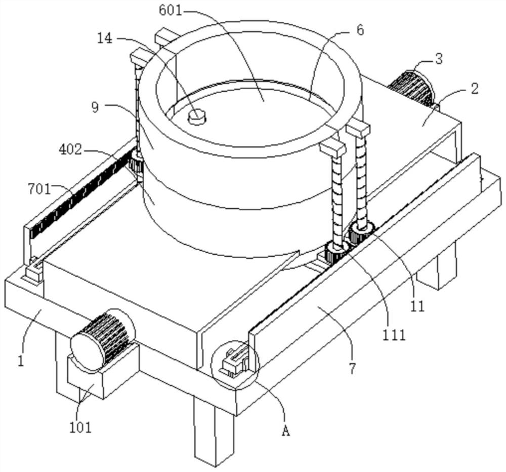
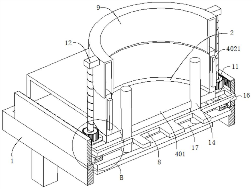
[0038] refer to Figure 1-10, a concrete manhole cover pouring mold, including a workbench 1, the two side walls of the workbench 1 are connected with a support seat 101, the outer wall of the support seat 101 is connected with a motor 3, and the top outer wall of the workbench 1 is connected with two support plates 2 , the outer walls of the two support plates 2 are connected with the first screw rod 201, the output end of the motor 3 passes through the support plate 2 and is fixedly connected with the first screw rod 201, and the outer walls of the two first screw rods 201 are screwed with sleeves 202, the top outer walls of the two sleeves 202 are respectively connected with the first set of molds 4 and the second set of molds 5, the first set of molds 4 and the second set of molds 5 move against each other, and the first set of molds 4 and the second set of molds 5 is provided with a pouring cavity 6, and a pouring part 601 is connected to the pouring cavity 6. The first s...

Embodiment 2

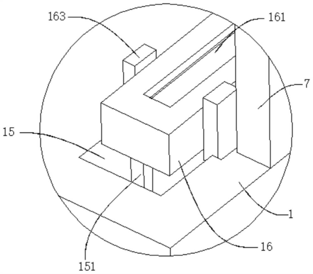
[0045] refer to Figure 1-10 , a concrete manhole cover pouring mold, which is basically the same as that of Embodiment 1, furthermore, the outer wall of the workbench 1 is excavated with a movable groove 15, the movable groove 15 is movably connected with a movable plate 16, and the outer wall of the movable plate 16 is excavated with a chute 161 A slider 162 is slidably connected to the inner wall of the chute 161 , and the slider 162 is fixedly connected to the bottom of the second screw rod 111 .

[0046] The outer wall of the movable plate 16 is connected with a guide bar 163 , and the inner wall of the movable groove 15 is dug with a guide groove 151 matched with the guide bar 163 .

[0047] The outer walls of the first base 401 and the second base 501 are dug with matching through holes 13, and the through holes 13 are movably connected with a movable rod 14, and the bottom of the movable rod 14 is connected with a movable plate 17, and the movable plate 17 is connected...


PUM


Abstract

The invention discloses a concrete well lid pouring mold and a pouring method thereof, and belongs to the technical field of constructional engineering. The concrete well lid pouring mold comprises aworkbench, wherein supporting bases are connected to the two side walls of the workbench, and motors are connected to the outer walls of the supporting bases; two supporting plates are connected to the outer wall of the top of the workbench, and first lead screws are connected to the outer walls of the two supporting plates; the output ends of the motors penetrate through the supporting plates andare fixedly connected with the first lead screws; the outer walls of the two first lead screws are in threaded connection with sleeves, and the outer walls of the tops of the two sleeves are connected with a first sleeve mold and a second sleeve mold correspondingly; the first sleeve mold movably abuts against the second sleeve mold; and a pouring chamber is formed between the first sleeve mold and the second sleeve mold. By controlling the motors to operate, the first sleeve mold and the second sleeve mold are separated, and a pouring piece can be conveniently and rapidly demolded. The moldis cleaned in the demolding process, so that the inner side of the mold is flat, then manual labor is saved, and the working efficiency is improved.

Description

technical field [0001] The invention relates to the technical field of construction engineering, in particular to a concrete manhole cover pouring mold and a pouring method thereof. Background technique [0002] Concrete pouring refers to the process of pouring concrete into molds until it is plasticized. In civil engineering, concrete and other materials are put into molds to make predetermined shapes. With the gradual improvement of municipal facilities in our country, there will be many underground pipelines in urban construction. , such as sewers, underground gas pipelines, tap water pipelines, power pipelines, communication pipelines, national defense pipelines, etc. These pipelines must have an outlet leading to the ground every other section. The section from the pipeline to the ground is called the inspection well. The ground is even, so a cover is needed, which is used to cover the lid of the inspection well, which is called the inspection well cover. The inspection...

Claims


Application Information

Patent Timeline
Patent Type & Authority Applications(China)
IPC IPC(8): B28B1/14B28B7/00B28B13/06
CPCB28B1/14B28B7/00B28B7/0035B28B13/065
Inventor 不公告发明人
Owner 广州市卓爵建筑工程有限公司
Learn More