Plate-rod type satellite main structure

A satellite main structure, plate-and-rod technology, applied in the direction of artificial satellites, space navigation equipment, space navigation aircraft, etc., can solve the problem of low local strength of the main load-bearing structure, low space utilization rate of the load-bearing tube, not suitable for scattered load and other issues, to achieve the effect of facilitating equipment layout, overcoming weak carrying capacity, and facilitating assembly operations

Active Publication Date: 2021-02-02
BEIJING INST OF SPACECRAFT SYST ENG
View PDF6 Cites 0 Cited by
  • Summary
  • Abstract
  • Description
  • Claims
  • Application Information

AI Technical Summary

Problems solved by technology

[0004] Bearing tube satellites are mostly used for medium-sized and large satellites, with relatively strong carrying capacity. The storage tanks are usually installed in series up and down, with a high center of mass and poor structural openness, which is unfavorable for equipment layout. inconvenient
The box-plate satellite has a flat equipment installation surface, large cabin capacity and is conducive to equipment layout, but the local strength of the box-plate satellite's main load-bearing structure is low, and the local load capacity of the connection between the plate and the docking ring is small, which is only suitable for small satellites
The truss-type satellite has a strong carrying capacity and is suitable for large and super-large-scale satellites. The truss-type satellite is mostly suitable for large-scale concentrated load transfer, and the concentrated load is transferred through the truss connection point. It is not suitable for decentralized load and highly integrated small and medium-sized satellites.

Method used


Image

  • Plate-rod type satellite main structure
  • Plate-rod type satellite main structure
  • Plate-rod type satellite main structure

Examples


Embodiment Construction

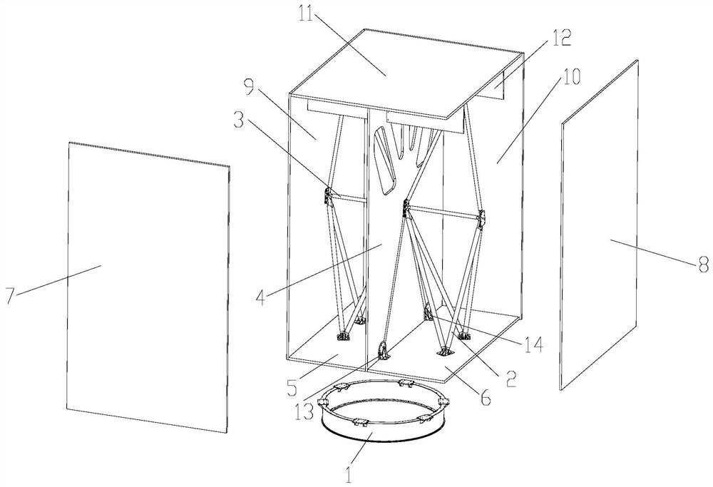
[0040]The present invention will be described in detail below with reference to the drawings and embodiments. Butt ring 1

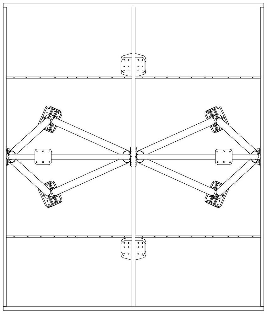
[0041]This embodiment provides a main structure of a slat-to-pole satellite, see AppendixFigure 1-2 , Including: butt ring 1, main bearing partition 4, first rod system 2, second rod system 3, first back floor 5, second back floor 6, counter floor 11 and four structural panels;

[0042]The docking ring 1 is an integral ring-shaped metal frame. The upper end of the docking ring 1 is provided with six main bearing connection flanges evenly distributed along its circumferential direction, and the lower end is a 1194A standard interface for docking with an external carrying interface ;

[0043]The four structural panels are the first structural panel 7, the second structural panel 8, the third structural panel 9 and the fourth structural panel 10; the first structural panel 7, the second structural panel 8, the third structural panel 9 and The fourth structural plates 10 ar...


PUM


Abstract

The invention discloses a plate-rod type satellite main structure which comprises a butt joint ring, a main force bearing partition plate, a first rod system, a second rod system and a rectangular boxbody. A main bearing connecting flange is arranged on the upper end surface of the butt joint ring; a back floor of the rectangular box body is fixed on the butt joint ring; the main force bearing partition plate is installed in the rectangular box body and divides an inner cavity of the rectangular box body into two identical cavities, and two force bearing beams with V-shaped structures are embedded in a panel of the main force bearing partition plate. The two ends of the V-shaped structure penetrate through the back floor and then are correspondingly connected with the main force bearing connecting flanges on the butt joint ring. The same first rod system and the same second rod system are respectively arranged in the two same cavities, respectively penetrate through the back floor andthen are connected with the main bearing connecting flanges on the butt joint rings in a one-to-one correspondence manner; the bearing capacity of the structure can meet the requirements of medium-sized satellites, the structural openness is good, general assembly operation is facilitated, equipment is convenient to arrange, the cabin capacity is large, the structural dry weight is small, and structural efficient bearing is achieved.

Description

Technical field[0001]The invention belongs to the technical field of spacecraft structures, and specifically relates to a plate-and-rod satellite main structure.Background technique[0002]The main function of the satellite's main bearing structure is: to withstand the dynamic and static loads of the satellite launch section to ensure that the structure is not damaged or deformed; to provide installation interfaces for on-board equipment and maintain stable accuracy.[0003]The main structure of the satellite has three commonly used structural forms, namely the bearing cylinder type, the box plate type and the truss type. The three types of satellites have their own characteristics.[0004]Bearing cylinder satellites are mostly used for medium and large satellites, with relatively strong carrying capacity. The storage tanks are usually installed in series up and down, with a high center of mass and poor structural openness, which is unfavorable to the equipment layout. The internal space ...

Claims


Application Information

Patent Timeline
Patent Type & Authority Applications(China)
IPC IPC(8): B64G1/10
CPCB64G1/10B64G1/223
Inventor 高峰陈燕王刚张玲王敏柴洪友张欢姜超余晨帆白刚陈茹
Owner BEIJING INST OF SPACECRAFT SYST ENG
Why Eureka
Try Eureka