Sealing head of bottle and can sealing machine

A sealing machine and oral technology, applied in the field of sealing equipment, can solve the problems of appearance damage, manual adjustment, and small rotation angle of the belt differential cover, and achieve the effects of good stability, not easy to stop for maintenance, and overcome the tilt of the cover.

Active Publication Date: 2021-02-02
HANGZHOU PROJECT & RES INST OF ELECTRO MECHANIC & LIGHT IND
View PDF7 Cites 0 Cited by
  • Summary
  • Abstract
  • Description
  • Claims
  • Application Information

AI Technical Summary

Problems solved by technology

At present, the widely used sealing machine in the market is used for sealing bottles and cans (such as canned food, tomato sauce, sauce, seafood products, etc.) by hanging cap type sealing, and the cap is sent to the bottle to be sealed by the cap unscrambling machine. When the can is put on, the lid is released and falls to the bottle mouth under the action of gravity. The lid is prone to deviation, and the hanging lid is tilted, resulting in the sealing cannot be carried out smoothly. It needs to be shut down for manual adjustment, which increases the uncertainty of the modern production line and affects the reliability of the equipment. Productivity and productivity
In addition, this type of sealing head adopts a belt differential screw cap, the rotation angle of the belt differential screw cap is small, and the friction between the belt and the paint print on the top surface of the cover is easy to cause defects such as appearance damage, and the belt differential screw cap The sealing machine output is low

Method used


Image

  • Sealing head of bottle and can sealing machine
  • Sealing head of bottle and can sealing machine
  • Sealing head of bottle and can sealing machine

Examples


Embodiment Construction

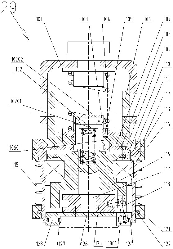
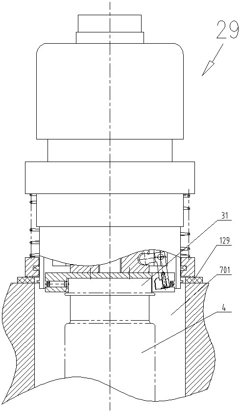
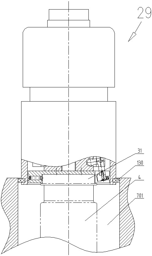
[0019] Such as Figures 1 to 4 As shown, the sealing head of a bottle and can sealing machine of the present invention, the bottle and can sealing machine can be a linear sealing machine, a single head sealing machine or a rotary sealing machine, preferably a rotary vacuum bottle and can sealing machine, the present invention It can be used for vacuum sealing and is suitable for rotary vacuum bottle and jar sealing machines.

[0020] Concrete structure of the present invention is as follows:

[0021] Such as figure 1 As shown, the sealing head 29 includes a sealing head cavity cover whose upper end is connected with a capping driving device, and a cap-taking and screwing mechanism arranged in the sealing head cavity cover is used to drive the screwing of the cap-taking and screwing mechanism. Cap driving mechanism, the cap-taking and screwing mechanism includes a disc-shaped (can also be square, oval, etc. other shapes) cap-removing device 126 arranged at the lower end of th...


PUM


Abstract

The invention discloses a sealing head of a bottle and can sealing machine, the sealing head comprises a sealing head cavity sleeve of which the upper end is connected with a cap screwing shaft, a captaking and screwing mechanism arranged in the sealing head cavity sleeve, and a cap screwing driving mechanism for driving the cap taking and screwing mechanism, the cap taking and screwing mechanismcomprises a cap taking device arranged at the lower end of the sealing head cavity sleeve, a concave cavity used for containing a cap is formed in the lower end of the cap taking device, at least twotelescopic elastic pieces arranged in the radial direction and used for jacking and clamping the cap are evenly distributed on the cavity wall of the concave cavity, at least two cap screwing claws used for jacking and clamping the cap are evenly distributed, the cap screwing claws are located at the lower end of a crank arm, the corner of the crank arm is hinged to the lower portion of a bearingpedestal, and the upper end of the crank arm is movably clamped in a clamping groove on an excircle of a positioning body core. According to the sealing head of the bottle and can sealing machine, automatic cap taking can be achieved, cap feeding is accurate and stable, cap sealing is stable, paint printing on the cap surface is not damaged during packaging, the sealing head is suitable for various cap screwing type bottle caps such as three-screw caps, four-screw caps and single-screw caps, and vacuum sealing can be achieved.

Description

technical field [0001] The invention relates to a sealing device for bottles and cans (such as cans, tomato sauce, seasoning sauce, seafood products, etc.), in particular to a sealing head of a bottle and can sealing machine. Background technique [0002] Twist-off cap bottles and cans, because of the different product characteristics and process properties in the can, the sealing methods can be divided into two categories: atmospheric pressure sealing and vacuum sealing. At present, the widely used sealing machine in the market is used for sealing bottles and cans (such as canned food, tomato sauce, sauce, seafood products, etc.) by hanging cap type sealing, and the cap is sent to the bottle to be sealed by the cap unscrambling machine. When the can is put on, the lid is released and falls to the bottle mouth under the action of gravity. The lid is prone to deviation, and the hanging lid is tilted, resulting in the sealing cannot be carried out smoothly. It needs to be shut...

Claims


Application Information

Patent Timeline
IPC IPC(8): B67B3/20
CPCB67B3/20
Inventor 陈新星王建勤朱理权童立上张洪亮冉茂杰
Owner HANGZHOU PROJECT & RES INST OF ELECTRO MECHANIC & LIGHT IND
Why Eureka
Try Eureka