
Eureka
For R&D, Eureka makes reading and utilizing patents & technical documents easy.
Eureka AIR
Designed for self-driven R&D workflows. Generate viable solutions, solve complex R&D challenges, empower your innovation with AI.

Eureka Materials
Designed for material experts only. Revolutionize your material R&D, from search, analyze, to developing new materials.

TechResearch
Generate reliable direction feasibility study reports for your R&D in just a few steps.

TechSeek
Discover and master advanced knowledge NOW. Basics, ideas, possibilities, all at once.

TechMind
As an expert in R&D Theories, TechMind can generates customized viable solutions instantly.

TechRisk
Analyze your overall solution with one click, know your potential R&D risks in advance.

TechMonitor
Get weekly tech updates, stay abreast of the latest tech innovations and key insights.
Variable displacement oil pump cavitation control method and device
A control method and oil pump technology, applied in pump control, lubrication pump, mechanical equipment, etc., can solve problems such as oil pump damage, engine bearing damage, inability to guarantee oil pump, etc., to reduce maintenance costs and avoid damage.
- Summary
- Abstract
- Description
- Claims
- Application Information
AI Technical Summary
Problems solved by technology
Method used
Image

Examples
Embodiment 1
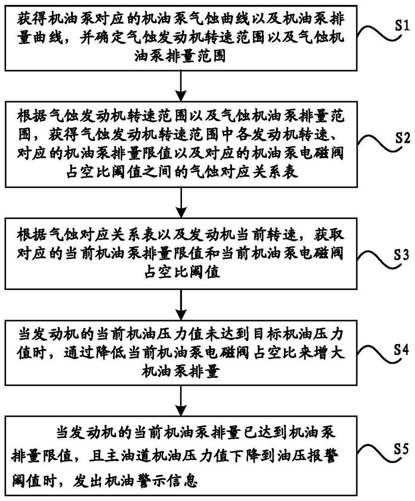
[0063] see Figure 1~3 As shown, the embodiment of the present invention provides a variable displacement oil pump cavitation control method, the method includes the following steps:
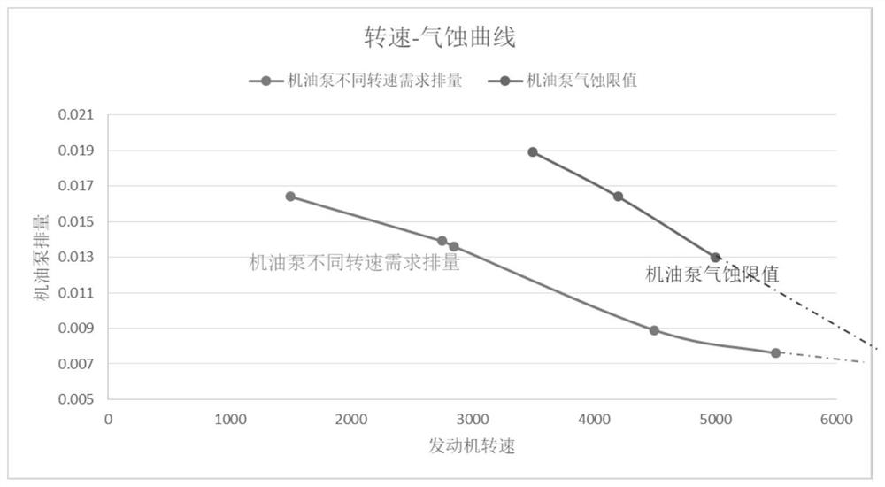
[0064] S1. Obtain the oil pump cavitation curve and the oil pump displacement curve corresponding to the oil pump, and determine the cavitation engine speed range and the cavitation oil pump displacement range;
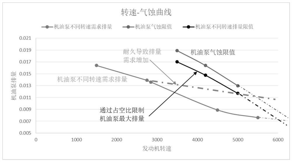
[0065] S2. According to the cavitation engine speed range and the cavitation engine oil pump displacement range, obtain the engine speed in the cavitation engine speed range, the corresponding oil pump displacement limit, and the corresponding oil pump solenoid valve duty cycle threshold. Correspondence table of cavitation;
[0066] S3. According to the cavitation correspondence table and the current engine speed, obtain the corresponding current oil pump displacement limit and current oil pump solenoid valve duty ratio threshold;
[0067] S4. When the current oil pressure value of th...
Embodiment 2
[0113] see Figure 4 As shown, the embodiment of the present invention provides a variable displacement oil pump cavitation control device, which includes:
[0114] The working parameter acquisition module is used to obtain the oil pump cavitation curve and the oil pump displacement curve corresponding to the oil pump, and determine the cavitation engine speed range and the cavitation oil pump displacement range;
[0115] The cavitation correspondence calculation module is used to obtain the engine speed in the cavitation engine speed range, the corresponding oil pump displacement limit and the corresponding oil pump electromagnetic Cavitation correspondence table between valve duty cycle thresholds;
[0116] A control basis calculation module, which is used to obtain the corresponding current oil pump displacement limit and the current oil pump solenoid valve duty cycle threshold according to the cavitation correspondence table and the current engine speed;
[0117] A cavit...
PUM
 Abstract
Description
Claims
Application Information
 - R&D Engineer
- R&D Manager
- IP Professional
- Industry Leading Data Capabilities
- Powerful AI technology
- Patent DNA Extraction
Browse by: Latest US Patents, China's latest patents, Technical Efficacy Thesaurus, Application Domain, Technology Topic, Popular Technical Reports.
© 2024 PatSnap. All rights reserved.Legal|Privacy policy|Modern Slavery Act Transparency Statement|Sitemap|About US| Contact US: help@patsnap.com