Pay-off device

A technology of pay-off device and rotating shaft, which is applied in transportation and packaging, mechanical equipment, brake type, etc., can solve the problems of difficult starting, difficult deceleration, high friction, etc., and achieve fast and effective braking, good braking effect, The effect of a small coefficient of friction

Inactive Publication Date: 2021-02-02
国网山东省电力公司昌邑市供电公司 +2
View PDF3 Cites 0 Cited by
  • Summary
  • Abstract
  • Description
  • Claims
  • Application Information

AI Technical Summary

Problems solved by technology

[0003] Aiming at the problems that the above-mentioned frictional force between the cable reel and the pay-off device is relatively large, and it is difficult to start and slow down, the present invention provides a pay-off device that adopts rolling friction and has a drum brake

Method used


Image

  • Pay-off device
  • Pay-off device
  • Pay-off device

Examples


Embodiment Construction

[0018] In order to make the purpose, features and advantages of the present invention more obvious and understandable, the technical solutions in the present invention will be clearly and completely described below in conjunction with the accompanying drawings in this specific embodiment. Obviously, the implementation described below Examples are only some embodiments of the present invention, but not all embodiments. Based on the embodiments in this patent, all other embodiments obtained by persons of ordinary skill in the art without creative efforts fall within the protection scope of this patent.

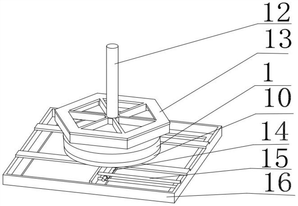
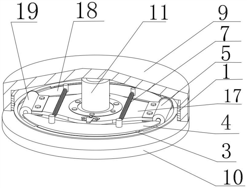
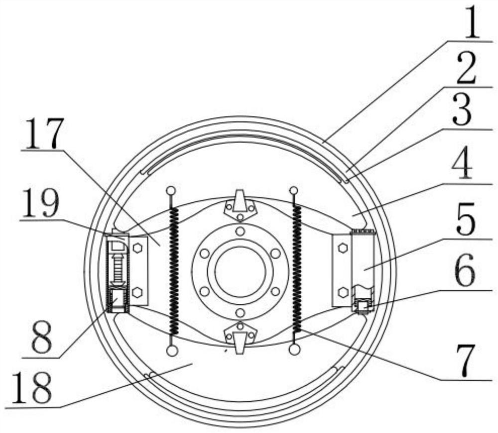
[0019] Such as figure 1 with figure 2 Shown, a kind of pay-off device, the bottom has the bottom bracket 16 of T-shaped, and axle base 10 is installed on the bottom bracket 16, and the top of axle base 10 is connected rotating shaft 9 through tapered roller bearing 11, and rotating shaft 9 and rotating shaft 9 are connected by tapered roller bearing 11. The sliding friction b...


PUM


Abstract

The invention discloses a pay-off device. According to the technical scheme, the pay-off device comprises a rotating shaft and a shaft seat, wherein the rotating shaft is an inverted pot body; the rotating shaft and the shaft seat are connected through a tapered roller bearing; a drum brake with a bidirectional double-leading-shoe structure is mounted on the tapered roller bearing; the bottom of the brake is connected with a brake arm; an opening through which the brake arm passes and moves is formed in the shaft seat; a bottom bracket is mounted at the bottom of the shaft seat; a limiting rodis arranged on the bottom bracket and is used for limiting the brake arm in the vertical direction; the top of a brake drum is connected with a tray bracket through a bolt; and the top of the tray bracket is fixedly connected with a vertical rod. The pay-off device has the beneficial effects that sliding friction between the rotating shaft and the shaft seat is converted into rolling friction through the tapered roller bearing, so that the friction coefficient is reduced, and the pay-off device is convenient to start; and the drum brake can brake the rotating shaft in rotation, so that the hidden dangers of cable extrusion, injury to people and the like caused by over-high rotating speed of a wire coil are prevented.

Description

technical field [0001] The invention relates to the technical field of pay-off equipment, in particular to a pay-off device. Background technique [0002] In the construction process of power medium and low voltage transformation and communication transformation, many places need to use power cables, communication cables, and communication optical cables. Since various cables (including power cables, communication cables, and communication optical cables, etc.) are wound in the cable reel, when the cables need to be used, they need to be supported by a pay-off bracket, and the cables are dragged by an external force to be unwound. During the pay-off process, due to the friction between the pay-off bracket and the cable reel, a large external force is required to drag the cable reel to rotate, and once the cable reel rotates at a high speed, it takes a lot of external force to make it The cable reel slows down, and there are hidden dangers such as cable extrusion and injury....

Claims


Application Information

Patent Timeline
Patent Type & Authority Applications(China)
IPC IPC(8): F16D51/10F16D65/28B65H49/26B65H63/00F16D121/14
CPCF16D51/10F16D65/28B65H49/26B65H63/00B65H2701/32B65H2701/34F16D2121/14
Inventor 姚文涛齐同飞王占超刘帅克蔡彬彬姚嘉敏李慧武海涛
Owner 国网山东省电力公司昌邑市供电公司
Why Eureka
Try Eureka