
Drying device for printing and dyeing of cloth

A drying device and fabric technology, applied in drying, drying machine, drying gas arrangement, etc., can solve the problems of different drying degrees, local temperature is difficult to find out the cause, and the quality of fabric drying is greatly affected. To achieve the effect of improving the drying quality

Active Publication Date: 2021-02-02
东阳市东岘针织服饰有限公司
View PDF11 Cites 0 Cited by
  • Summary
  • Abstract
  • Description
  • Claims
  • Application Information

AI Technical Summary

Problems solved by technology

[0002] Cloth needs to be dried after printing and dyeing. The drying temperature control has a great influence on the quality of cloth drying. Conventional drying equipment can only simply adjust the overall drying temperature of the equipment, and cannot adjust the local temperature. I don't even know the specific temperature, and local temperature changes will directly affect the drying quality of the cloth. Therefore, it is even difficult to find out the reason for the difference in local temperature in conventional drying equipment, and conventional equipment may still There are problems such as dyeing liquid dripping that affects the heating equipment, drying on one side leads to different degrees of drying on both sides or low drying efficiency. If we can accurately know and control the temperature changes inside the drying equipment, we will be able to Greatly improve the drying quality of the cloth

Method used


Image

  • Drying device for printing and dyeing of cloth
  • Drying device for printing and dyeing of cloth
  • Drying device for printing and dyeing of cloth

Examples


Embodiment Construction

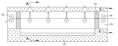
[0017] Combine below Figure 1-7 The present invention is described in detail, and for convenience of description, the orientations mentioned below are now stipulated as follows: figure 1 The up, down, left, right, front and back directions of the projection relationship itself are the same.

[0018] refer to Figure 1-7 According to an embodiment of the present invention, a drying device for cloth printing and dyeing includes a body 10, a through cavity 15 runs through between the left and right surfaces of the body 10, and left and right sides are fixedly connected between the upper and lower walls of the through cavity 15. A partition 13 with a symmetrical position, the left side of the partition 13 on the left side is provided with an up and down symmetrical extrusion cylinder that is rotatably connected between the front and rear walls of the through cavity 15 and used to squeeze out excess dye in the cloth 12. The right side of the partition 13 on the right side is pro...


PUM


Abstract

The invention discloses a drying device for printing and dyeing of cloth. The drying device comprises a machine body, wherein a through cavity is formed between the left surface and the right surfaceof the machine body in a penetrating mode; partition plates which are symmetrical in the left-right direction are fixedly connected between the upper wall and the lower wall of the through cavity; theleft side of the partition plate on the left side is provided with extrusion cylinders which are rotationally connected between the front wall and the rear wall of the through cavity, are used for extruding out redundant dye in the cloth and are symmetric in the vertical direction; temperature adjustment and control can be automatically performed; the temperature of gas before and after drying can be reflected in real time; meanwhile, the temperature of each internal area can be accurately controlled and displayed; and once the temperature of each area is greatly different, the height difference between a wedge-shaped rod and a second scale rod can be quickly amplified and fed back in real time, so that the temperature of each internal area can be accurately controlled, then the drying quality of the cloth is greatly improved, furthermore, the cloth can be dried on two sides at the same time, and the influence of dye liquor dripping on heating equipment does not need to be worried about.

Description

technical field [0001] The invention relates to the technical field related to printing and dyeing, in particular to a drying device for cloth printing and dyeing. Background technique [0002] Cloth needs to be dried after printing and dyeing. The drying temperature control has a great influence on the quality of cloth drying. Conventional drying equipment can only simply adjust the overall drying temperature of the equipment, and cannot adjust the local temperature. I don't even know the specific temperature, and local temperature changes will directly affect the drying quality of the cloth. Therefore, it is even difficult to find out the reason for the difference in local temperature in conventional drying equipment, and conventional equipment may still There are problems such as dyeing liquid dripping that affects the heating equipment, drying on one side leads to different degrees of drying on both sides or low drying efficiency. If we can accurately know and control ...

Claims


Application Information

Patent Timeline
Patent Type & Authority Applications(China)
IPC IPC(8): F26B13/04F26B13/28F26B21/00F26B21/10D06B15/00D06B15/02
CPCF26B13/001F26B13/28F26B21/004F26B21/10D06B15/02D06B15/00
Inventor 魏文杰
Owner 东阳市东岘针织服饰有限公司
Learn More