Phase identification method by utilizing electron diffraction

An electron diffraction and diffraction ring technology, which is used in material analysis, measurement devices, and instruments using wave/particle radiation, and can solve problems such as small grain size, strong preferred orientation, and difficult phase identification.

Active Publication Date: 2021-02-02
MINZU UNIVERSITY OF CHINA
View PDF5 Cites 0 Cited by
  • Summary
  • Abstract
  • Description
  • Claims
  • Application Information

AI Technical Summary

Problems solved by technology

However, the rising nanomaterials have the characteristics of small crystal grains, poor crystallinity, and strong preferred orientation. In X-ray diffraction, only a small number of diffraction peaks appear, and even only broadened diffraction bumps appear, which greatly improves the accuracy of phase identification. In transmission electron microscopy, although these nanomaterials can be observed in real time, in many cases it is difficult to tilt and record electron diffraction patterns with multiple axes on the same grain, and it is difficult to carry out accurate phase identification

Method used


Image

  • Phase identification method by utilizing electron diffraction
  • Phase identification method by utilizing electron diffraction
  • Phase identification method by utilizing electron diffraction

Examples


Embodiment 1 2

[0066] The phase identification of embodiment 1 titanium dioxide

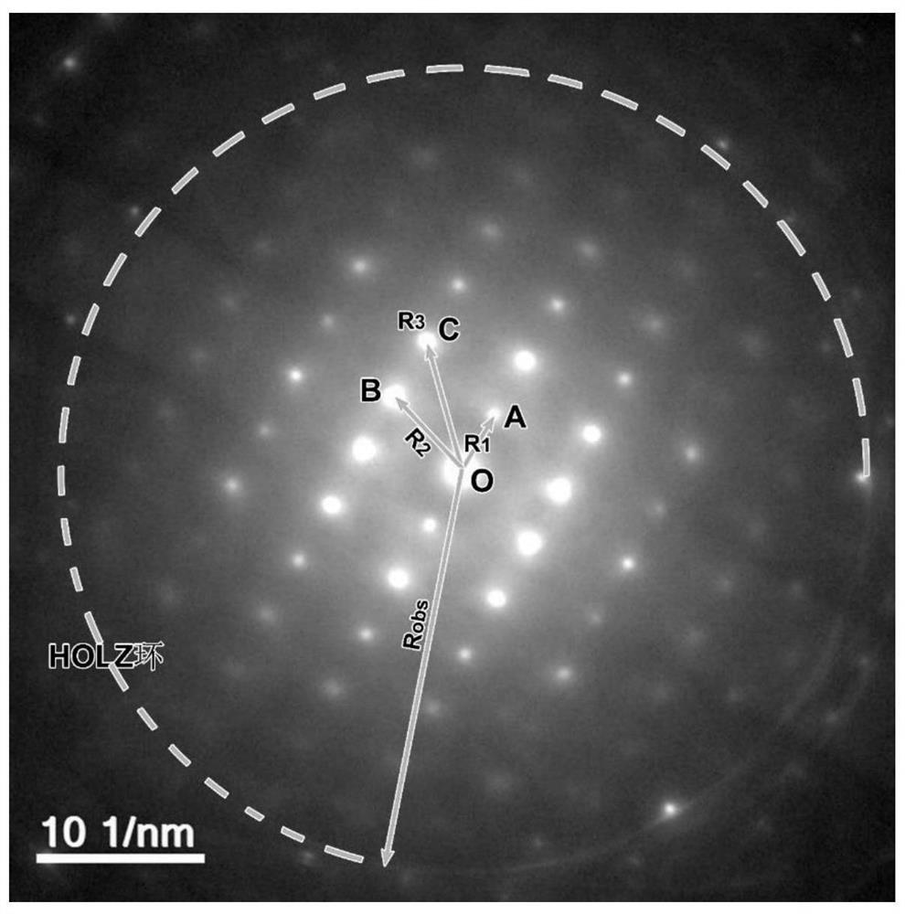
[0067] 1) Record an axial electron diffraction pattern containing high-order Laue diffraction rings of titanium dioxide (titanium dioxide gel sintered at 500°C for 6 hours), as shown in figure 2 . The electron diffraction pattern was recorded with a JEOL JEM-2100 transmission electron microscope at 200 kV, camera length L = 100 mm.

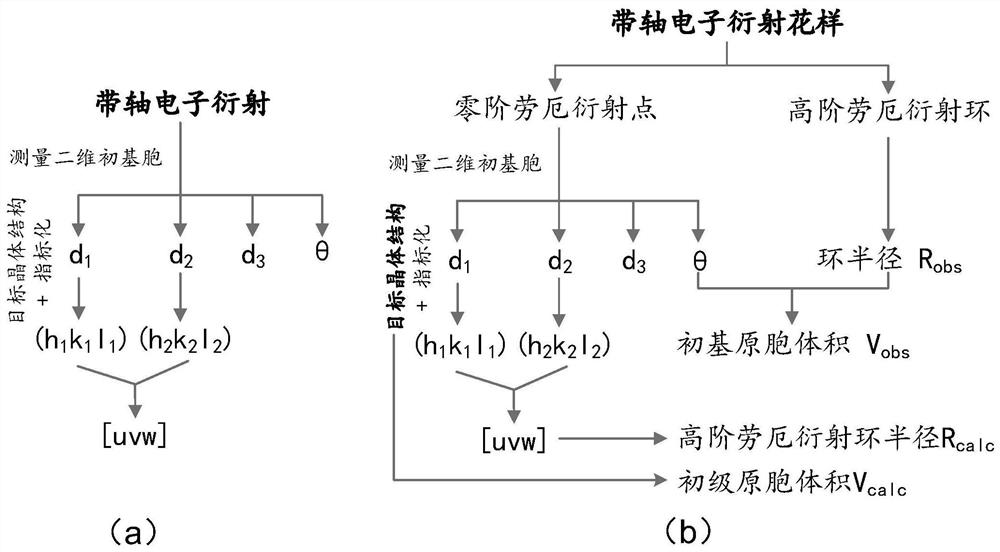
[0068] 2) Measure the zero-order Laue diffraction point and the radius of the high-order Laue diffraction ring of titanium dioxide;

[0069] Take the transmission spot as the origin O of the two-dimensional primordial cell, and take the nearest neighbor diffraction points A and B as the adjacent edges to construct a two-dimensional primordial cell, as figure 2 shown. Measure OA, OB, OC (OC is the diagonal) and ∠AOB (where ∠AOB=72.2°) and R obs , thus getting R 1 , R 2 , R 3 and θ. According to the formula Rd=Lλ, where For the wavelength of the 200kV electron beam, calcu...

Embodiment 2

[0096] Example 2 Phase recognition of titanium dioxide prepared by hydrothermal method

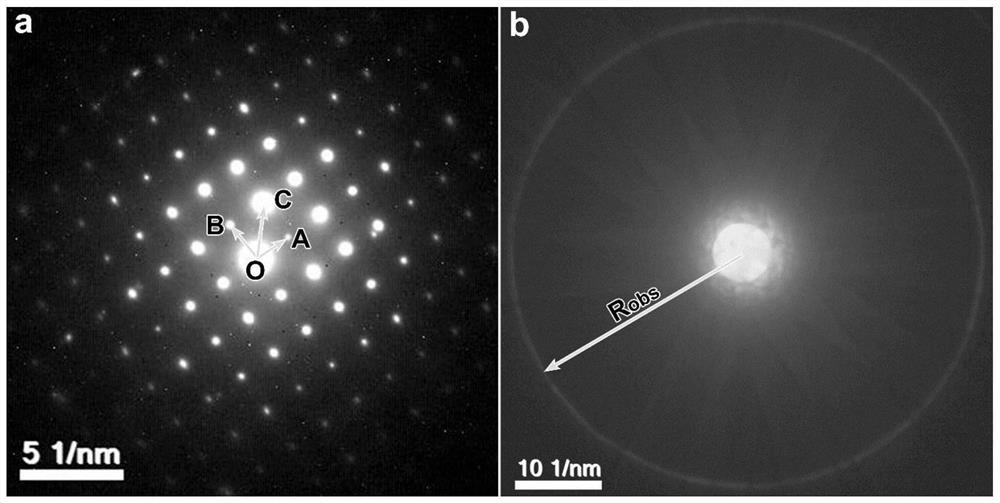
[0097] 1) Titanium dioxide nanocrystals prepared by hydrothermal method have small crystal grains and poor crystallinity, so it is difficult to record zero-order Laue diffraction points and high-order Laue diffraction rings on the same electron diffraction pattern. To this end, we use a JEOL JEM-2100 transmission electron microscope to record the zero-order Laue diffraction points of the crystal grains by nanobeam electron diffraction at 200kV, and the high-order Laue diffraction rings by converging beam electron diffraction. The camera length L=100mm, such as image 3 shown in a-b.

[0098] 2) Measure the radius of the zero-order Laue diffraction point and the high-order Laue diffraction ring;

[0099] Take the transmission spot as the origin O of the two-dimensional primordial cell, and take the nearest neighbor diffraction points A and B as the adjacent edges to construct a two-dimens...


PUM

PropertyMeasurementUnit
radiusaaaaaaaaaa

Abstract

The invention provides a new phase identification method by utilizing an electron diffraction pattern. The method can be used for identifying the phase of a material of which the chemical components are known but the crystal structure of the material cannot be determined, and is particularly suitable for occasions where a plurality of diffraction patterns are difficult to obtain. The method has the advantages that only one electron diffraction pattern with the axis containing the high-order Laue diffraction ring needs to be recorded, or one zero-order Laue diffraction point pattern and one corresponding high-order Laue diffraction ring pattern need to be recorded on the crystal grain of the same crystal to be detected; although the Brorafig of the crystal to be detected cannot be completely determined, the measured radius and primitive cell volume of the high-order Laue diffraction ring are compared with a calculation result of a target structure so that the indexing accuracy can be improved, alternative phases which do not meet conditions can be effectively filtered, and the phase analysis accuracy is greatly improved; and the working efficiency is obviously improved in actual electron microscope experiments and data analysis.

Description

technical field [0001] The invention relates to a method for identifying crystal phases by using electron diffraction patterns, and belongs to the technical field of material microstructure characterization and crystal structure analysis. Background technique [0002] Phase identification is a basic link in the process of material preparation and characterization, which solves the problem of "what" the material to be tested. The main means of phase identification are X-ray powder diffraction and electron diffraction. The phase identification of X-ray powder diffraction is to compare whether the diffraction peak of the powder sample to be tested matches the diffraction peak on the standard card (Powder diffraction file, referred to as PDF card). If the peak positions and peak intensities of all diffraction peaks in the experiment can match the PDF card, it means that the structure of the sample to be tested is consistent with the crystal structure represented by the PDF card...

Claims


Application Information

Patent Timeline
Patent Type & Authority Applications(China)
IPC IPC(8): G01N23/20058G01N23/2055
CPCG01N23/20058G01N23/2055
Inventor 施洪龙
Owner MINZU UNIVERSITY OF CHINA
Why Eureka
Try Eureka