
Automatic adjustment control system and method for segmental prefabricated assembled beam formwork

A prefabricated assembly and automatic adjustment technology, applied in the control/regulation system, program control in sequence/logic controller, non-electric variable control, etc., can solve the problem of not being able to give ten adjustment points, and reduce manual measurement. The probability of errors, the reduction of the probability of input errors, the effect of improving the turnover efficiency

Pending Publication Date: 2021-02-02
山东淄博环宇桥梁模板有限公司
View PDF6 Cites 0 Cited by
  • Summary
  • Abstract
  • Description
  • Claims
  • Application Information

AI Technical Summary

Problems solved by technology

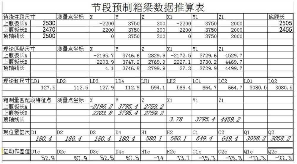
[0004] The traditional formwork control system generally controls the four lifting and lowering oil cylinders of D1-4, the two independently controlled rotations of H1 and H2 and the lateral movement of C1 and C2 to control the oil cylinders, and the front and rear movement control of the walking trolley to control Q1 and Q2 to achieve matching beam sections. For attitude position adjustment, it is impossible to give the data of how much each of the ten adjustment points should be adjusted during measurement. It can only be based on the continuous running-in between the surveyor and the formwork worker. Because of the three-dimensional adjustment process, when correcting a deviation in one direction, it is likely to produce the other two. The deviation in one direction, and the traditional drive has no numerical control measures, and the adjustment amount needs the experience and feel of the operator. According to the estimated situation of the measurement data, repeated adjustment-measurement-adjustment-measurement..., after running-in proficiently, often This process also takes about two hours, and this process accounts for about one-eighth of the working time of the template turnover cycle.

Method used


Image

  • Automatic adjustment control system and method for segmental prefabricated assembled beam formwork
  • Automatic adjustment control system and method for segmental prefabricated assembled beam formwork

Examples


Embodiment Construction

[0032] The present invention will be described in further detail below in conjunction with the accompanying drawings.

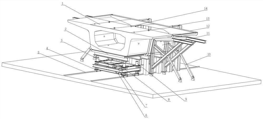
[0033] combine figure 1 As shown, the segmental prefabricated assembled beam formwork automatic adjustment control system includes digital twin technology, numerical control electric screw drive rod device and numerical control measurement system 13, matching beam segment 1, bottom mold trolley 3 and longitudinal moving track 5, the bottom mold The trolley 3 is connected and arranged on the longitudinal moving track 5 through a numerical control electric screw drive rod device, the bottom formwork 2 is connected above the bottom formwork trolley 3, the matching beam section 1 is arranged on the bottom formwork 2, and the matching beam section 1 is provided with a fixed end formwork 12 on the rear side, the numerical control measurement system 13 is set on the fixed end formwork 12, the numerical control measurement system 13 is connected with the digital twin...


PUM


Abstract

The invention discloses an automatic adjustment control system for a segmental prefabricated assembled beam formwork, which comprises a digital twinning technology, a numerical control electric spiraldriving rod device, a numerical control measurement system, a matched beam segment, a bottom die trolley and a longitudinal moving track, and the bottom die trolley is connected to the longitudinal moving track through the numerical control electric spiral driving rod device, a bottom die plate is connected above the bottom die trolley, the matching beam section is arranged on the bottom die plate, the fixed end die plate is arranged on the rear side of the matching beam section, the numerical control measuring system is arranged on the fixed end die plate, the numerical control measuring system is connected with a digital twinning technology, and a beam top measuring point is arranged on the upper surface of the matching beam section. Compared with the prior art, the device has the advantages of being convenient to use and operate and capable of being adjusted and controlled in place at a time.

Description

technical field [0001] The invention relates to the technical field of segmental prefabricated assembled beam templates, in particular to an automatic adjustment control system and control method for segmental prefabricated assembled beam templates. Background technique [0002] The overall horizontal curve of the segmental prefabricated assembled beam is approaching the arc by gradually joining the right-angled trapezoid in the horizontal direction, and the longitudinal curve is also approaching the arc by gradually joining the vertical right-angled trapezoid. Therefore, the segmental beam of the curved section is often one end face perpendicular to the web of the bottom plate, and the other end face may have a certain angle with the longitudinal center axis of the bottom face and the vertical plane. [0003] The traditional formwork system required for precast construction generally consists of a fixed end formwork, a bottom formwork perpendicular to it, and other vertical...

Claims


Application Information

Patent Timeline
Patent Type & Authority Applications(China)
IPC IPC(8): G05B19/05G05D3/12G05D5/00
CPCG05B19/05G05D3/12G05D5/00
Inventor 张继忠郭法传郭凯刘成于涛贾晓娜周剑吕涛张延军崔建峰李超黄福坤
Owner 山东淄博环宇桥梁模板有限公司
Learn More