Eureka AIR delivers breakthrough ideas for toughest innovation challenges, trusted by R&D personnel around the world.

Engine oil pump cavitation improvement method and device

A technology of oil pump and engine, which is applied in the direction of engine components, machine/engine, engine lubrication, etc., and can solve problems such as unfavorable oil pump improvement

Active Publication Date: 2021-02-02
DONGFENG MOTOR CORP HUBEI
View PDF15 Cites 2 Cited by
  • Summary
  • Abstract
  • Description
  • Claims
  • Application Information

AI Technical Summary

Problems solved by technology

[0006] However, the existing technical solutions are limited by the volume of the oil pump and the optimization accuracy, which is not conducive to the improvement of the oil pump by technicians. Therefore, an engine oil pump air pump is urgently needed. Corrosion improvement technology to solve technical problems at this stage

Method used


Image

  • Engine oil pump cavitation improvement method and device
  • Engine oil pump cavitation improvement method and device
  • Engine oil pump cavitation improvement method and device

Examples


Embodiment 1

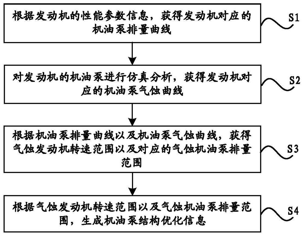
[0060] see Figures 1 to 4 As shown, an embodiment of the present invention provides a method for improving cavitation of an engine oil pump, the method comprising the following steps:

[0061] S1. Obtain the oil pump displacement curve corresponding to the engine according to the performance parameter information of the engine;

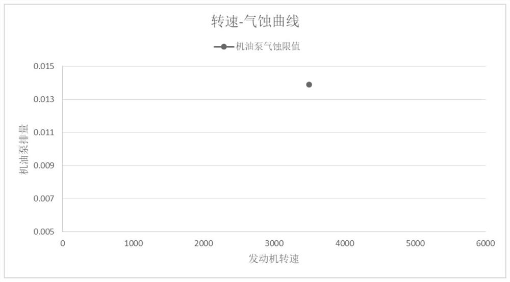
[0062] S2. Perform simulation analysis on the oil pump of the engine to obtain the cavitation curve of the oil pump corresponding to the engine;

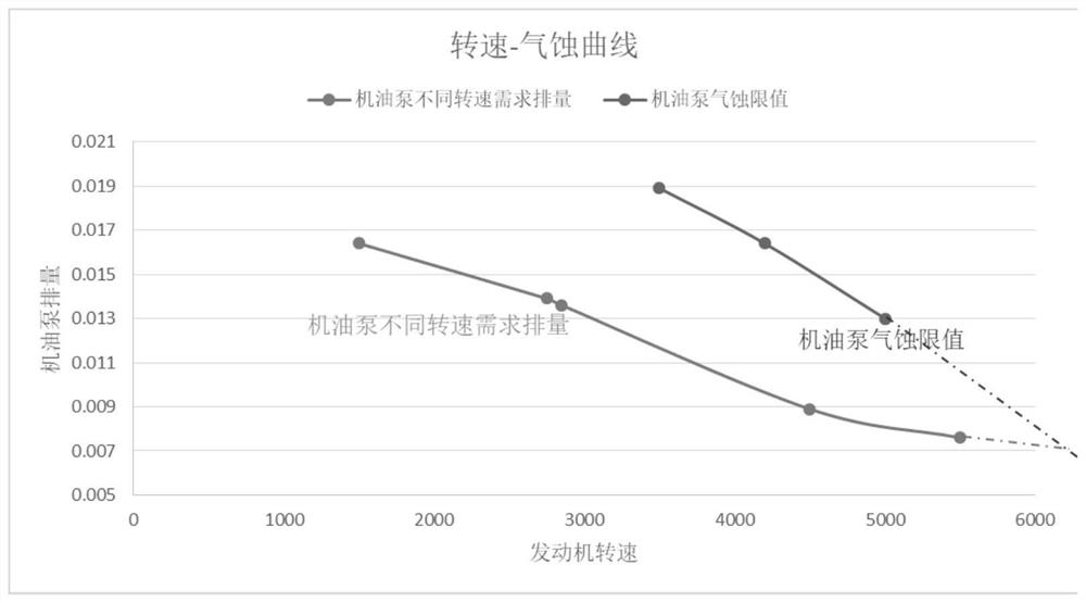
[0063] S3. According to the oil pump displacement curve and the oil pump cavitation curve, obtain the cavitation engine speed range and the corresponding cavitation oil pump displacement range;

[0064] S4. Generate oil pump structure optimization information according to the speed range of the cavitation engine and the displacement range of the cavitation oil pump.

[0065] In the embodiment of the present application, step S1 is first performed. According to the flow resistance characteristics, flow re...

Embodiment 2

[0096] see Figure 5 As shown, an embodiment of the present invention provides a device for improving cavitation of an engine oil pump, the device comprising:

[0097] The displacement curve drawing module is used to obtain the displacement curve of the oil pump corresponding to the engine according to the performance parameter information of the engine;

[0098] The cavitation curve drawing module is used to simulate and analyze the oil pump of the engine, and obtain the cavitation curve of the oil pump corresponding to the engine;

[0099] The range calculation module is used to obtain the speed range of the cavitation engine and the corresponding displacement range of the cavitation oil pump according to the oil pump displacement curve and the oil pump cavitation curve;

[0100] The structure optimization calculation module is used for generating the structure optimization information of the oil pump according to the speed range of the cavitation engine and the displacemen...


PUM


Abstract

The invention relates to an engine oil pump cavitation improvement method and device, and relates to the technical field of engines. The method comprises the following steps: acquiring an oil pump displacement curve corresponding to an engine according to performance parameter information of the engine; carrying out simulation analysis on an oil pump of the engine to obtain an oil pump cavitationcurve corresponding to the engine; according to the oil pump displacement curve and the oil pump cavitation erosion curve, acquiring the cavitation erosion engine rotating speed range and the corresponding cavitation erosion oil pump displacement range; and according to the cavitation engine rotating speed range and the cavitation engine oil pump displacement range, generating oil pump structure optimization information. Based on the oil pump displacement curve and the oil pump cavitation erosion curve, the cavitation erosion engine rotating speed range and the corresponding cavitation erosionoil pump displacement range are determined and used for improving the oil pump in a targeted mode, high precision is achieved, and the cavitation erosion improving effect is improved.

Description

technical field [0001] The invention relates to the technical field of engines, in particular to a method and device for improving cavitation of an engine oil pump. Background technique [0002] At this stage, in order to comply with the requirements of engine energy conservation and emission reduction, the following three changes have occurred in the engine: 1. More and more engines use vane type variable displacement oil pumps; The displacement is getting larger and larger; 3. Considering the good performance of the engine, the volume requirements for parts such as the oil pump tend to be stricter. [0003] The above three restrictions will cause the oil pump to have a small volume and a large displacement. At this time, the oil pump is prone to cavitation at the usual engine speed, resulting in damage to the oil pump and engine bearing bushes. [0004] The cavitation of the oil pump is generally caused by the following reasons: 1. The pump suction flow is too large, whic...

Claims


Application Information

Patent Timeline
IPC IPC(8): G06F30/20G06F30/28F04C14/28F16N13/20F01M1/02
CPCG06F30/20G06F30/28F04C14/28F16N13/20F01M1/02Y02T90/00
Inventor 欧阳丹施发义张丽珠查乃敏丁伟
Owner DONGFENG MOTOR CORP HUBEI
Why Eureka
Eureka Blog
Learn More