Near-shore marine communication enhancement equipment

A marine and equipment technology, which is applied in the field of near-shore marine communication enhancement equipment, can solve the problems that the tower antenna cannot be built too high, the top antenna cannot be made too large, and the recovery and storage are troublesome. Signal transmission and reception capability, the effect of improving the signal transmission and reception effect

Inactive Publication Date: 2021-02-02
上海云冉信息科技有限公司
View PDF0 Cites 3 Cited by
  • Summary
  • Abstract
  • Description
  • Claims
  • Application Information

AI Technical Summary

Problems solved by technology

[0004] Therefore, at present, many larger near-shore ships are equipped with ship-borne signal base stations, and the antennas of ship-borne signal base stations are still more traditional models. The traditional traditional tower antenna cannot be built too high, and the top antenna cannot be made too large
[0005] At present, there is a technology to raise the antenna to a high place through a helium (hydrogen) balloon. Among them, the antenna is easily damaged if it is attached to the outside of the balloon, and it is inconvenient to retract the antenna if it is placed inside the balloon.
For marine use, it needs to be retracted frequently (the balloon antenna needs to be retracted in severe weather such as strong winds, thunderstorms, and unattended at night), although the helium (hydrogen) balloon can be deflated and retracted, but the shape of the internal antenna It is still fixed, so it is very troublesome to retrieve, store and store, and the retracting and retracting of the helium (hydrogen) balloon is achieved by exhausting and inflating, so every time sending and receiving consumes a lot of helium, so it is necessary to configure enough helium Tanks, which both increase the burden and increase the cost

Method used


Image

  • Near-shore marine communication enhancement equipment
  • Near-shore marine communication enhancement equipment
  • Near-shore marine communication enhancement equipment

Examples


Embodiment Construction

[0030] In order to make the technical means, creative features, goals and effects achieved by the present invention easy to understand, the present invention will be further described below in conjunction with specific embodiments.

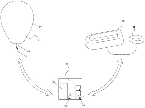
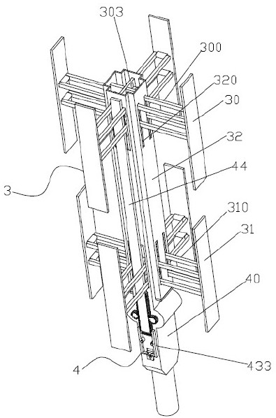
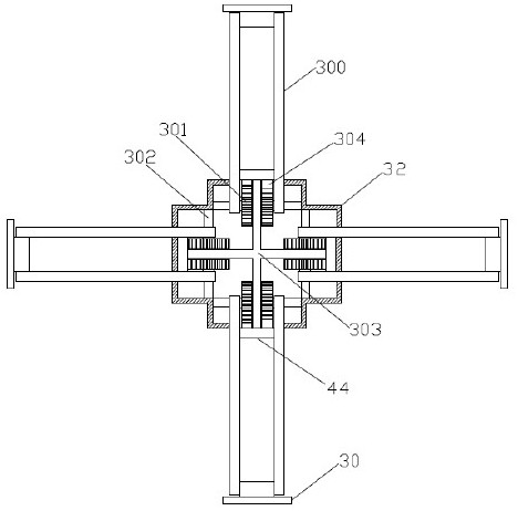
[0031] Such as Figure 1 to Figure 8 As shown, a near-shore marine communication enhancement device includes a marine base station 01 and a balloon antenna 2. The balloon antenna 2 is connected to the marine base station 01 through a cable 21. The balloon antenna 2 is composed of an outer balloon 20 and an inner balloon Antenna assembly 3 and working assembly 4 are made up, and described antenna assembly 3 comprises upper antenna 30, lower antenna 31 and middle tube 32, and described upper antenna 30 and lower antenna 31 are respectively provided with four pieces, and four pieces of upper antenna 30 and lower antenna 31 The upper connecting rod 300 and the lower connecting rod 310 are rotatably connected to the four side walls of the intermediate ...


PUM


Abstract

The invention discloses near-shore marine communication enhancement equipment which comprises a marine base station and a balloon antenna, the balloon antenna is connected with the marine base stationthrough a cable, the balloon antenna is composed of an outer balloon, an antenna assembly and a working assembly, the antenna assembly and the working assembly are arranged in the outer balloon, theantenna assembly comprises an upper antenna, a lower antenna and a middle pipe, and the signal receiving and transmitting effect is improved. Helium in the balloon antenna and helium in a rubber boat(swim ring) can be communicated, the same part of gas plays a role in lifting off the balloon antenna and manufacturing the rubber boat (swim ring), a helium tank does not need to be carried, the antenna part is located in the balloon, the antenna can be folded and unfolded, the balloon antenna can be folded conveniently, and the storage is convenient. And after unfolding, the signal transceivingeffect is improved. The folding and unfolding of the antenna are driven by inflation and deflation, extra driving equipment is not needed, the weight and size of the balloon antenna are reduced, and the operation is convenient.

Description

technical field [0001] The invention relates to the field of mobile communication, in particular to a communication enhancement device for coastal ships. Background technique [0002] As society progresses more and more, people's demand for the Internet is also increasing. The 5G communication infrastructure that is currently being actively laid is also in full swing, but it is basically concentrated on populated land, especially in cities. This results in very poor signals in places like oceans, large lakes, etc. [0003] Therefore, after many ships go to sea, it is often difficult to use network services. Ocean-going ships can only use satellite signals, while ships in rivers and lakes and near-shore ships (cruise ships, ferries, fishing boats, etc.) can still receive weak shore-based signals due to their proximity to land. [0004] Therefore, at present, many larger near-shore ships are equipped with ship-borne signal base stations, and the antennas of ship-borne signa...

Claims


Application Information

Patent Timeline
Patent Type & Authority Applications(China)
IPC IPC(8): H01Q1/08H01Q1/00H01Q1/34
CPCH01Q1/002H01Q1/082H01Q1/34
Inventor 付玲玲伍小莉张素英
Owner 上海云冉信息科技有限公司
Why Eureka
Try Eureka