Outdoor support with high wind resistance and for 5G antenna installation

An external bracket and antenna technology, applied in the field of outdoor brackets, can solve problems such as jamming, antenna strength weakening, and 5G antenna height cannot be changed, and achieve the effects of reducing rust, accelerating water evaporation, and enhancing 5G signal transmission and reception

Inactive Publication Date: 2021-02-02
陈俊翔
View PDF0 Cites 3 Cited by
  • Summary
  • Abstract
  • Description
  • Claims
  • Application Information

AI Technical Summary

Problems solved by technology

[0002] The antenna can enhance the device’s transmission and reception of 5G signals. The 5G antenna is often installed in a high place outdoors to reduce the building’s obstruction to the signal. However, the outdoor wind is strong, and the antenna is installed and fixed with a strong outdoor bracket. The bracket has a The telescopic rods cooperate with each other, and the height of the antenna can be changed by adjusting the telescopic rods; in the prior art, when the outdoor bracket is used to install and fix th

Method used


Image

  • Outdoor support with high wind resistance and for 5G antenna installation
  • Outdoor support with high wind resistance and for 5G antenna installation
  • Outdoor support with high wind resistance and for 5G antenna installation

Examples


Embodiment 1

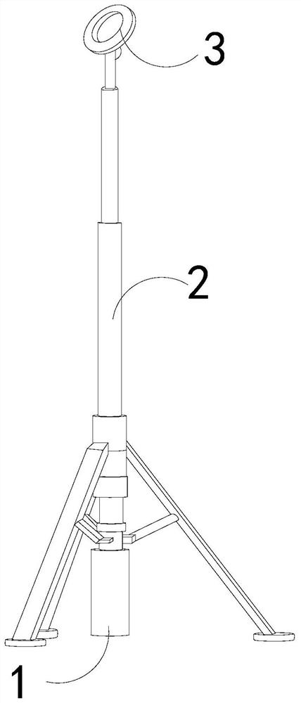
[0027] as attached figure 1 to attach Figure 5 Shown:

[0028] The present invention provides an outdoor bracket with strong wind resistance for 5G antenna installation. Its structure includes a base 1, a telescopic rod 2, and an antenna clip 3. The telescopic rod 2 is movably matched with the top of the base 1. 3 is fixed on telescopic rod 2 tops.

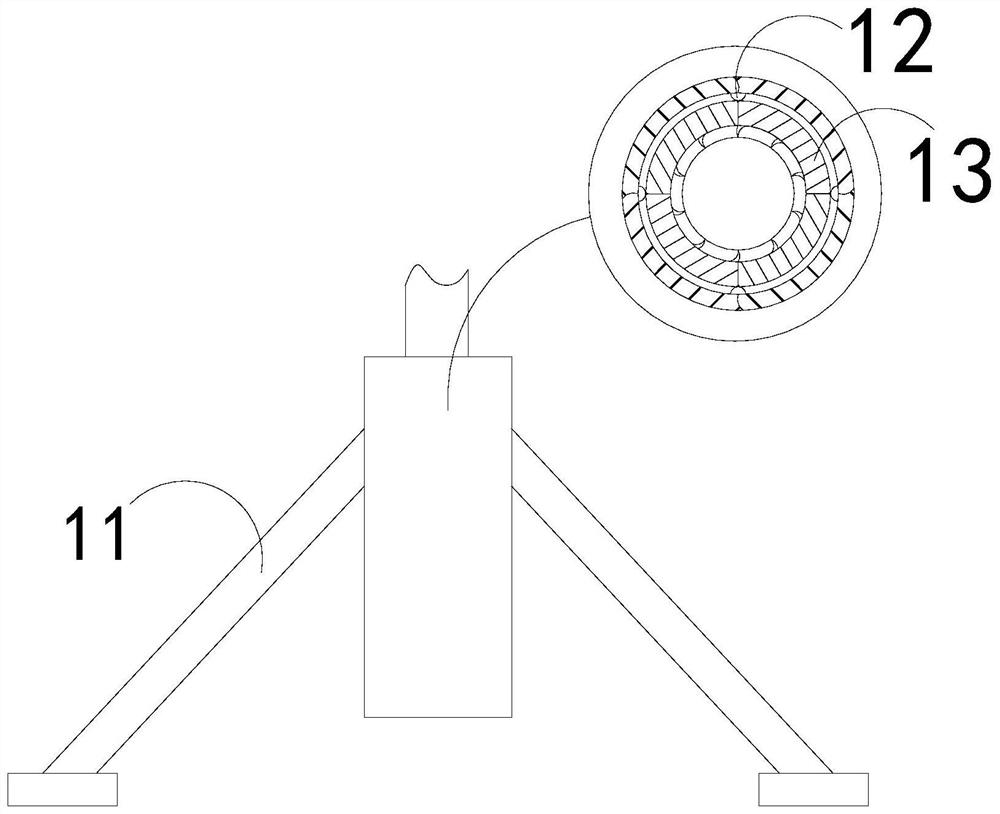
[0029] The base 1 is provided with a support rod 11, a support block 12, and a clearing mechanism 13. The support rod 11 is obliquely welded on the outer wall of the base 1, and the clearing mechanism 13 is fixed inside the base 1 by the support block 12. The telescopic rod 2 Through the middle of the support block 12.

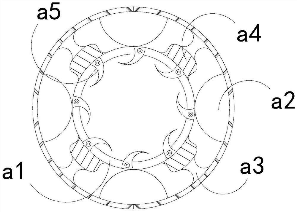
[0030] Wherein, the clearing mechanism 13 is provided with an inner ring a1, a heat sink a2, a limit block a3, a push block a4, and a contact tooth a5, the inner ring a1 is located inside the clearing mechanism 13, and the heat sink a2 is fixed on the clearing mechanism 13 inner wall, the limit block a3 is em...

Embodiment 2

[0036] as attached Figure 6 to attach Figure 8 Shown:

[0037] Wherein, the heat sink a2 is provided with a bottom plate e1, a telescopic plate e2, a contact plate e3, and an air hole e4, the bottom plate e1 is located below the heat sink a2, and the telescopic plate e2 is fixed above the bottom plate e1, The contact plate e3 is set at the center of the top of the expansion plate e2, and the air hole e4 runs through the two sides of the expansion plate e2. The expansion plate e2 is made of rubber and has elasticity, which is conducive to the deformation and reset of the expansion plate e2 so that the inside of the heat sink a2 The gas is squeezed and diffused toward the air hole e4, and the upper surface of the contact plate e3 has raised dots, which is beneficial to increase the force-bearing area of ​​the top and speed up the movable cooperation with the inner ring a1.

[0038]Wherein, the inner ring a1 is provided with an elastic strip r1, an opening r2, and a blocking ...


PUM


Abstract

The invention discloses an outdoor support with high wind resistance and for 5G antenna installation. The outdoor support structurally comprises a base, a telescopic rod and an antenna clamp, whereinthe telescopic rod is movably matched with the interior of the top end of the base. Due to the fact that a protective paint layer on the outer wall of the telescopic rod falls off after long-term friction, the protective paint layer is clamped between threads and is gradually compacted, so the telescopic rod is clamped in the telescopic process; the protective paint layer on the outer wall of thetelescopic rod is removed through a brush plate of a removing mechanism, so accumulation of the protective paint layer in threads on the outer wall of the telescopic rod is reduced, jamming of the base and the telescopic rod in the telescopic process is reduced, the height of the 5G antenna is normally changed, and 5G signal receiving and transmitting of the antenna are enhanced; rainwater easilyenters the base along a gap between the base and the telescopic rod in rainy days, and internal gas is diffused to the base through deformation of a heat dissipation device, so the speed air flowing in the base is increased, water evaporation in the base is accelerated, rusting of the outer wall of the telescopic rod is reduced, and a movable fitting speed of the telescopic rod and the base is increased.

Description

technical field [0001] The invention belongs to the field of 5G antennas, and more specifically, relates to an outdoor bracket with strong wind resistance for 5G antenna installation. Background technique [0002] The antenna can enhance the device’s transmission and reception of 5G signals. The 5G antenna is often installed in a high place outdoors to reduce the building’s obstruction to the signal. However, the outdoor wind is strong, and the antenna is installed and fixed with a strong outdoor bracket. The bracket has a The telescopic rods cooperate with each other, and the height of the antenna can be changed by adjusting the telescopic rods; in the prior art, when the outdoor bracket is used to install and fix the 5G antenna, because the telescopic rods cooperate with each other through threads, the protective paint layer on the outer wall of the telescopic rods will be rubbed for a long time After falling off, the protective paint layer is sandwiched between the thread...

Claims


Application Information

Patent Timeline
IPC IPC(8): H01Q1/12H01Q1/00H01Q1/10
CPCH01Q1/02H01Q1/10H01Q1/12
Inventor 陈俊翔
Owner 陈俊翔
Why Eureka
Try Eureka