Positive multi-electrode multi-pole spark plug

A multi-pole, spark plug technology, applied in the field of spark plugs, can solve problems such as unreliable work, small application range of spark plugs, and inability to adjust, so as to improve stability and service life, increase effective working mileage, and overcome poor ignition effect Effect

Pending Publication Date: 2021-02-02
韦坤明 +1
View PDF1 Cites 0 Cited by
  • Summary
  • Abstract
  • Description
  • Claims
  • Application Information

AI Technical Summary

Problems solved by technology

There is a defect in the side electrode: it is a single-point ignition when used, the ignition effect is poor, the fuel is not fully burned, the work is unreliable, and carbon deposits often occur, which makes the spark plug ignition invalid
Since the ceramic insulator of the above-mentioned positive multipolar spark plug is a sealed design, it fills the inner cavity of the metal shell, and when the engine is idling and low speed, the oil and carbon deposits generated will accumulate on the surface of the ceramic insulator, which is easy to make the metal The shell 6 and the cross-shaped electrode piece 8 are adhered to form a loop grounding, which will cause the spark plug to fail to ignite and the working mileage to be short.
[0006] In addition, there is another defect in this kind of positive multipolar spark plug. Since the ceramic insulator is a sealed design, there is no heat chamber (air chamber) in the spark plug, so the calorific value of the spark plug is constant and cannot be adjusted. , cannot adapt to the different calorific value requirements of various engines, especially for the geographical characteristics of China across multiple latitudes, the calorific value requirements of engines used at different latitudes are usually different (the difference in outdoor temperature is large), so this The scope of application of spark plugs is small, which is not conducive to large-scale promotion

Method used


Image

  • Positive multi-electrode multi-pole spark plug
  • Positive multi-electrode multi-pole spark plug
  • Positive multi-electrode multi-pole spark plug

Examples


Embodiment Construction

[0029] Below, the present invention will be further described in conjunction with the accompanying drawings and specific implementation methods. It should be noted that, under the premise of not conflicting, the various embodiments described below or the technical features can be combined arbitrarily to form new embodiments. .

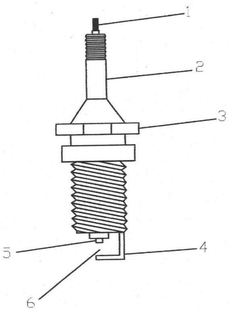
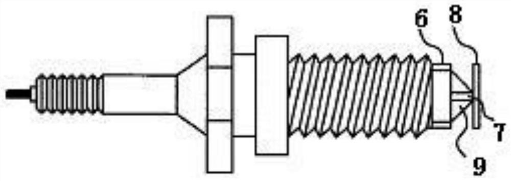
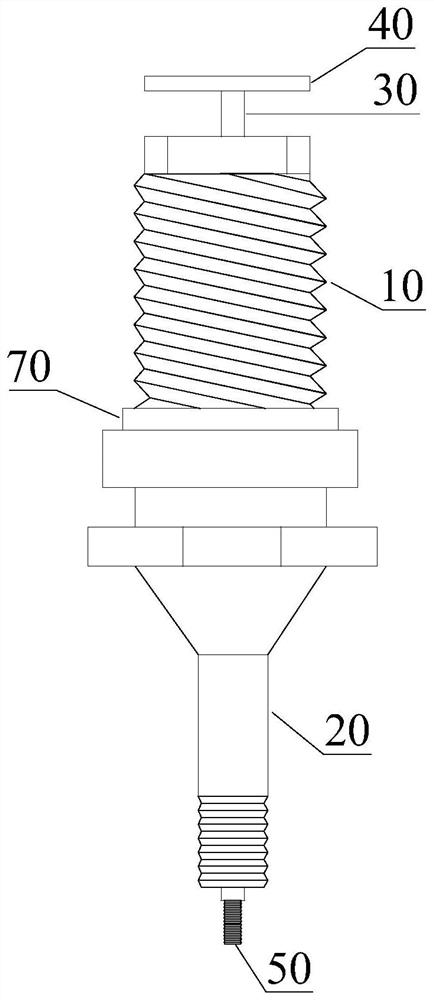
[0030] refer to Figure 3-Figure 5 , the present invention discloses a positive multi-pole multi-pole spark plug, including: a metal shell 10, a ceramic insulator 20, a center electrode 30, an electrode piece 40 and a connection screw 50. Wherein, the metal shell 10 is a structure with upper and lower openings, and the inner cavity of the metal shell 10 is fixedly provided with a ceramic insulator 20, and the connecting screw 50 is connected to the center electrode 30, and the connecting screw 50 and the center electrode 30 are coaxially arranged in the ceramic insulator 20, and the center One end of the electrode 30 extends out of the ceramic insulat...


PUM


Abstract

The invention discloses a positive multi-electrode multi-pole spark plug, which comprises a metal shell, a ceramic insulator, a central electrode, an electrode plate and a wiring screw rod, wherein the ceramic insulator is fixedly arranged in an inner cavity of the metal shell, the wiring screw rod is connected with the central electrode, the wiring screw rod and the central electrode are both arranged in the ceramic insulator, one end of the central electrode extends out of the ceramic insulator and is fixedly connected with the electrode plate, the electrode plate comprises at least two electrodes, and the electrodes are located above the metal shell. And a cavity is formed between the ceramic insulator and the inner side wall of the metal shell to form a hot chamber. The phenomenon of ignition failure of the spark plug caused by loop grounding due to adhesion of deposited carbon generated by insufficient fuel combustion between the electrode plate and the metal shell under the idling and low-speed operation conditions of the engine is avoided; in addition, the heat value of the spark plug can be adjusted according to the heat value requirements of different engines, so that thespark plug can be suitable for various different engines.

Description

technical field [0001] The invention relates to the field of spark plugs, in particular to a positive multi-pole multi-pole spark plug. Background technique [0002] Automobiles and motorcycles are the main means of transportation. Especially in the trend of urbanization, the development of motor vehicles provides a platform and foundation for the accelerated pace of life and the improvement of production efficiency. If the engine is the heart of the car, the spark plug is the pacing part of the whole heart, which is the premise and basis for ensuring the efficiency and quality of the engine. A problem with the spark plug of the car will cause practical problems such as engine starting and running, vibration, fuel consumption and other practical problems, which will affect the normal function of the car, and will bring negative impacts on driving safety and comfort, as well as the realization of environmental protection goals. worsening effect. [0003] At present, the mor...

Claims


Application Information

Patent Timeline
Patent Type & Authority Applications(China)
IPC IPC(8): H01T13/20H01T13/22H01T13/40H01T13/54
CPCH01T13/20H01T13/22H01T13/40H01T13/54
Inventor 韦坤明原春玲黎超
Owner 韦坤明
Why Eureka
Try Eureka