Method for testing fatigue damage of inorganic binding material stabilizing material

An inorganic binder, fatigue damage technology, applied in the direction of testing the strength of materials by applying a stable bending force, can solve the problems of uneven surface of the test piece, damage problems, and inability to obtain test results, etc., to achieve easy implementation and simple operation Effect

Inactive Publication Date: 2011-11-23
山东省交通科学研究所
View PDF2 Cites 11 Cited by
  • Summary
  • Abstract
  • Description
  • Claims
  • Application Information

AI Technical Summary

Problems solved by technology

Due to reasons such as loading, molding, and health preservation, the bending and tensile strengths of beam specimens of the same batch are not exactly the same. The damage phenomenon is common, which makes the stress concentration during the loading process, which causes the fatigue test data to vary greatly, and it is impossible to obtain accurate and reliable test results. This is also the reason why the existing fatigue test methods for inorganic binder stabilized materials are difficult to implement.
Another important problem is that the existing fatigue test methods only have t

Method used


Image

  • Method for testing fatigue damage of inorganic binding material stabilizing material
  • Method for testing fatigue damage of inorganic binding material stabilizing material
  • Method for testing fatigue damage of inorganic binding material stabilizing material

Examples


Embodiment

[0037] Inorganic binder stabilized material fatigue damage test method of the present invention comprises the following steps (taking lime fly ash stabilized gravel material fatigue damage test as example):

[0038] a) Vibration formed girder specimen

[0039] In this embodiment, 4 stress ratios are used, and each stress ratio requires at least 5 fatigue test samples, that is, 3 girder specimens are required for one stress ratio, so a total of 12 girder specimens are required.

[0040] Lime-fly ash-stabilized macadam material girder specimens were formed using a vibrating table. The length × width × height of the girder specimen is 550mm × 150mm × 150mm.

[0041] In the height direction, the material is loaded in two layers. The bottom layer is 75mm high, and the material is evenly loaded. On one side, use a wooden stick with a diameter of about 2cm to insert and tamp. After installation, level the surface and compact it slightly, and then place it on a vibrating table for m...


PUM

PropertyMeasurementUnit
Unconfined compressive strengthaaaaaaaaaa

Abstract

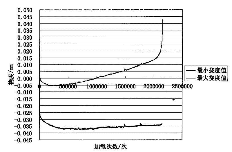
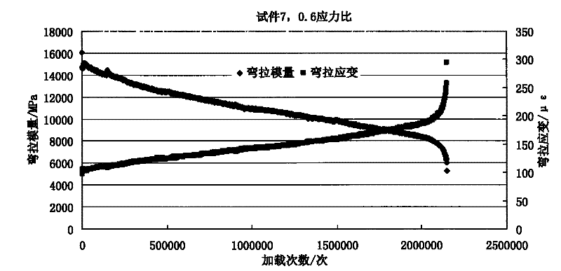
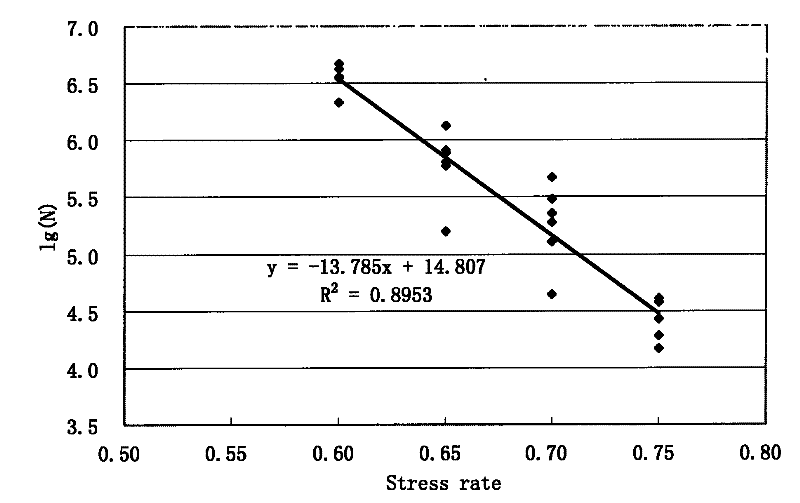
The invention discloses a method for testing the fatigue damage of an inorganic binding material stabilizing material, and belongs to the field of road engineering. The method comprises the following steps of: cutting a vibration moulding large beam test piece serving as matrix into a plurality of small beam test pieces which meet the specification, determining the fatigue load of the small beam test pieces on the same layer through the bending strength test of the small beam test pieces on the same layer, performing four-point bent beam dynamic repeat load test on the basis, measuring the central deflection change of small beams in the test process to obtain the decay law of dynamic bending modulus along with fatigue load frequency in the approximately actual stress state, and the growthlaw of the bending stress along with the fatigue load frequency, and performing the repeat load test under the conditions of different stress ratios according to the method to obtain the fatigue damage life of the inorganic binding material stable broken stone material. Compared with the conventional fatigue test method, the method overcomes the technical problems of large fatigue failure load frequency variation and low reliability of a fatigue equation in the conventional fatigue test method, realizes the accurate estimation of the fatigue life of the inorganic binding material stable broken stone material, discloses the fatigue damage law of the inorganic binding material stable material, improves the reliability of road design and has good popularization and application value.

Description

technical field [0001] The invention relates to the field of road engineering, in particular to a method for testing fatigue damage of inorganic binder stabilized materials. Background technique [0002] In my country's high-grade highways, semi-rigid base materials are widely used, but engineering practice shows that the early damage of semi-rigid base is serious. In the design and evaluation of the laboratory, the semi-rigid base material only uses simple indicators such as material composition, compressive strength, and static modulus as design standards, and does not conduct in-depth damage evaluation and dynamic mechanical response indicators and parameters that are consistent with the actual stress state of the road surface. test. The existing simple fatigue test method attempts to represent the bending and tensile strength of a part of the beam specimens formed in the same batch as the average value of the bending and tensile strength of this batch of specimens, and ...

Claims


Application Information

Patent Timeline
IPC IPC(8): G01N3/20
Inventor 韦金城余四新王林马士杰崔世萍
Owner 山东省交通科学研究所
Why Eureka
Try Eureka