Array-type multi-channel fiber-process Fabry-Perot pressure sensor and pressure measurement method

A sensing device and Fab sensor technology, which is applied in fluid pressure measurement using optical methods, and measurement of the change force of optical properties of materials when they are stressed, can solve the problems of spectral working spectrum width, optical power jitter, Optical characteristics limitations and other issues, to achieve the effect of overcoming high-speed switching, switching speed improvement, and easy channel expansion

Active Publication Date: 2012-12-19
TIANJIN UNIV
View PDF5 Cites 11 Cited by
  • Summary
  • Abstract
  • Description
  • Claims
  • Application Information

AI Technical Summary

Problems solved by technology

Optical switches can be divided into two categories: mechanical and non-mechanical. Mechanical optical switches are moved by optical fibers or optical components to change the optical path to achieve channel switching. The advantages are low insertion loss, high isolation, and no polarization. and wavelength, the disadvantage is that the switching time is long, the optical power jitters at the moment of switching, the switching times are limited and the repeatability is poor
Non-mechanical optical switches rely on electro-optical effects, magneto-optic effects, acousto-optic effects, and thermo-optic effects to change the refractive index of the waveguide and change the optical path. The advantage of this type of optical switch is that the switching time is short, which can reach milliseconds or even shorter, but Due to the limitation of the optical characteristics of the device material, the spectral working spectrum is usually narrow and cannot work in the visible light band

Method used


Image

  • Array-type multi-channel fiber-process Fabry-Perot pressure sensor and pressure measurement method
  • Array-type multi-channel fiber-process Fabry-Perot pressure sensor and pressure measurement method
  • Array-type multi-channel fiber-process Fabry-Perot pressure sensor and pressure measurement method

Examples


Embodiment Construction

[0033] The specific implementation, structure, features and effects provided by the present invention will be described in detail below in conjunction with the accompanying drawings and preferred embodiments.

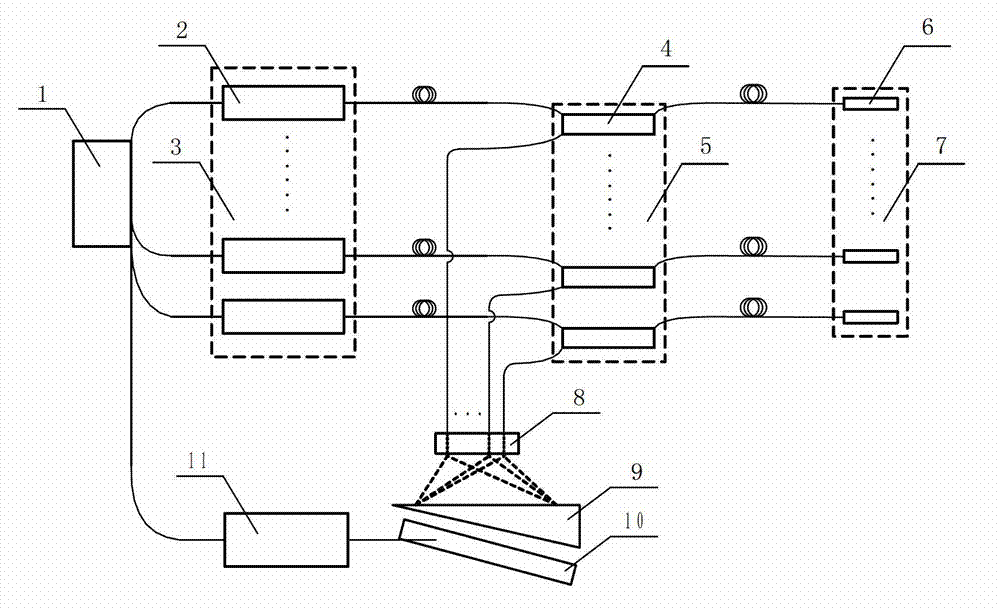
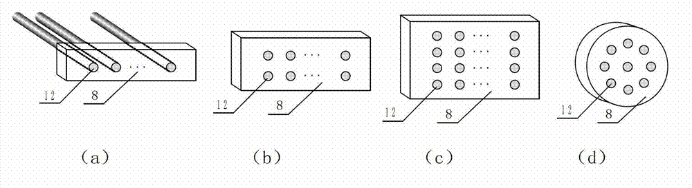
[0034] Such as figure 1 As shown, the array multi-channel fiber optic Fabry pressure sensing device includes: LED light source modulation module 1, LED light source array 3 composed of LED light source 2, fiber optic coupler array 5 composed of fiber coupler 4, and fiber optic Fabry sensor 6. The fiber optic sensor array 7, the fiber array 8, the optical wedge 9, the linear array CCD10 and the signal processing unit 11. Wherein, the optical fiber output ends 12 of the optical fiber array 8 are arranged in a certain lattice shape, including a single-row dot matrix structure, a double-row dot matrix structure, a multi-row dot matrix structure or a circular dot matrix structure, such as figure 2 shown.

[0035] An LED light source 2, an optical fiber Fab sensor 6 and an...


PUM


Abstract

The invention discloses an array-type multi-channel fiber-process Fabry-Perot pressure sensor and a pressure measurement method. From the input end to the output end, the pressure sensor is sequentially provided with an LED (light-emitting diode) light source array (3) composed of an LED light source modulation module (1) and LED light sources (2), a fiber coupler array (5) composed of fiber couplers (4), a fiber Fabry-Perot sensor array (7) composed of fiber Fabry-Perot sensors (6), a demodulation light path module composed of a fiber array (8), an optical wedge (9) and a linear array CCD (charge-coupled device) (10), and a signal processing unit (11). Compared with the prior art, by combining the LED light source array modulation with the fiber array structure, the invention implements sequential quick demodulation of multiple fiber Fabry-Perot pressure sensors by using a single demodulation light path, and solves the problem that the traditional light switch structure can not simultaneously meet the requirements of high-speed switching, low loss and high reliability; and the channel expansion is easy, so that the number of the sensing channels can be up to 64.

Description

technical field [0001] The invention relates to the field of optical fiber sensing, in particular to an array type multi-channel optical fiber Fabry pressure sensing device based on LED light source modulation and a pressure measurement method thereof. Background technique [0002] The fiber optic Fabry pressure sensor usually consists of a Fabry-Perot microresonator cavity formed by the end face of an optical fiber and the end face of a diaphragm. The pressure acts on the diaphragm to deform the diaphragm, resulting in a change in the length of the Fabry cavity, thereby realizing sensing. Due to such structural characteristics, the fiber optic Fabry pressure sensor cannot realize series wavelength division multiplexing like fiber gratings, and its multi-channel realization needs to be switched by optical switches. Optical switches are commonly used in optical switching systems in optical fiber transmission, and are widely used in multi-channel optical fiber sensing systems....

Claims


Application Information

Patent Timeline
Patent Type & Authority Applications(China)
IPC IPC(8): G01L1/24G01L11/02
Inventor 刘铁根江俊峰王双刘琨尹金德王少华孟祥娥张以谟吴凡秦尊琪
Owner TIANJIN UNIV
Why Eureka
Try Eureka