Circuit board welding quality detection method and device

A welding quality and detection method technology, which is applied in the field of circuit board welding quality detection, can solve problems such as fatigue, low efficiency, and difficulty in ensuring reliability, and achieve the effects of overcoming low reliability, low false detection rate, and high work efficiency

Pending Publication Date: 2019-11-19
深圳市格灵人工智能与机器人研究院有限公司
View PDF3 Cites 11 Cited by
  • Summary
  • Abstract
  • Description
  • Claims
  • Application Information

AI Technical Summary

Problems solved by technology

However, whether it is traditional manual welding or modern welding, there will be welding defects of components. Here, it is mainly for the installation of components and the detection of high-warping defects in welding, and it is necessary to design this set, because traditional There are some deficiencies in the manual detection method. Manual detection is too subjective, and it is easy to fatigue after long-term work, so the quality of detection cannot be guaranteed. For some small-sized parts, it is difficult to guarantee the reliability of detection manually, and the efficiency is low, which cannot meet the actual detection needs.

Method used


Image

  • Circuit board welding quality detection method and device
  • Circuit board welding quality detection method and device

Examples


Embodiment 1

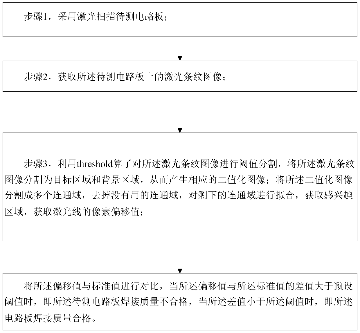
[0043] Use laser to scan the circuit board to be tested. After obtaining the laser image, process its binarized image (the grayscale image with 256 brightness levels is selected through appropriate threshold value and can still reflect the overall and local characteristics of the image).

[0044] Taking advantage of the difference in grayscale characteristics between the target area (laser stripe) to be extracted and its black background in the image, the image is regarded as a combination of two types of areas (target area and background area) with different gray levels, and it is more reasonable to choose one The threshold to determine whether each pixel in the image should belong to the target area or the background area, so as to generate a corresponding binary image.

[0045] The threshold selection method is to use the threshold(Image1,Regions1,48,253) operator to segment the acquired image in halcon, because the contrast between the target area and the background area is...

Embodiment 2

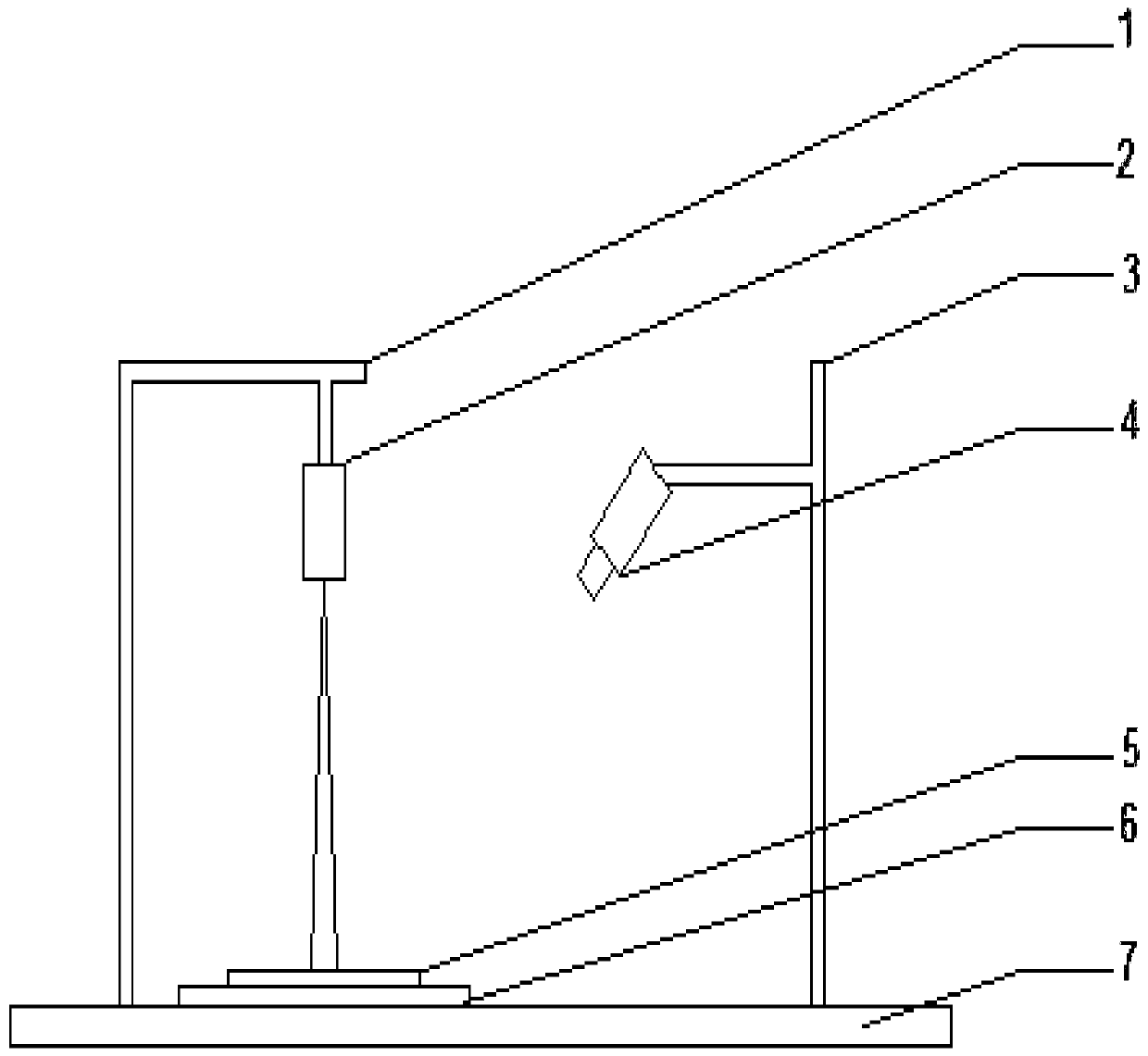
[0062] In this embodiment, the laser module is a red laser with a line width of <100m and an output angle of 60 degrees, and the image acquisition module is an Advantech 5-megapixel network port camera.

[0063] like figure 2 As shown, it shows a circuit board welding quality inspection device, including two support structures 1 and 3, which are respectively the support of the laser 2 and the support of the camera 4, and the laser 2 and the camera 4 are respectively fixed at the top position In terms of angle and angle, the camera 4 and the laser 2 are placed on the same horizontal line. Preferably, the optical axis of the camera 4 forms an angle of 45 degrees with the working platform 7 . And ensure that the entire circuit board 5 is within the field of view of the camera. The circuit board 5 of the product under test is directly below the laser 2. The circuit board 5 is placed on the mobile support plate 6. The guide rails on the mobile support plate 6 and the working platf...


PUM


Abstract

The invention discloses a circuit board welding quality detection method and device. The method comprises the following steps: scanning a to-be-detected circuit board by adopting laser; acquiring a laser stripe image on the circuit board to be detected; processing the laser stripe image to obtain an offset value of a laser line; and comparing the deviation value with a standard value, when the difference value between the deviation value and the standard value is greater than a preset threshold value, determining that the welding quality of the circuit board to be tested is unqualified, and when the difference value is less than the preset threshold value, determining that the welding quality of the circuit board is qualified. According to the invention, the deviation value of the laser ray is obtained, and the deviation value is compared with the standard value to judge whether the laser ray is qualified or not, so that the problems of low reliability and low efficiency of a traditional manual detection method are solved, and the automatic detection of a machine, high working efficiency and low false detection rate are realized.

Description

technical field [0001] The invention relates to the field of circuit board quality detection, in particular to a circuit board welding quality detection method and device. Background technique [0002] Printed Circuit Board (Printed Circuit Board), referred to as PCB board, is the carrier of various electronic components, providing physical connections for microelectronic components of various sizes and functions, and is the most basic electronic component. With the continuous development of integrated circuit technology, the welding method of components has also undergone some changes. However, whether it is traditional manual welding or modern welding, there will be welding defects of components. Here, it is mainly for the installation of components and the detection of high-warping defects in welding, and it is necessary to design this set, because traditional There are some deficiencies in the traditional manual inspection method. Manual inspection is too subjective, an...

Claims


Application Information

Patent Timeline
Patent Type & Authority Applications(China)
IPC IPC(8): G06T7/00G06T7/11G06T7/187G06T7/194G01B11/25G01B11/06G01N21/956
CPCG06T7/0004G06T7/11G06T7/187G06T7/194G01B11/2518G01B11/0608G01N21/956G06T2207/30141G06T2207/30152G01N2021/95638G01N2021/95646
Inventor 于波韩玉杨延竹
Owner 深圳市格灵人工智能与机器人研究院有限公司
Why Eureka
Try Eureka