Supercharge Your Innovation With Domain-Expert AI Agents!

10kV-oriented semi-automatic switch trolley push-pull device

A technology of switch trolley and push-pull device, which is applied in the direction of switchgear, switchgear parts, substation/switch layout details, etc., which can solve the problems of low automation and achieve the effect of simplifying push-pull and reducing labor intensity

Pending Publication Date: 2021-02-02
STATE GRID TIANJIN ELECTRIC POWER +1
View PDF5 Cites 0 Cited by
  • Summary
  • Abstract
  • Description
  • Claims
  • Application Information

AI Technical Summary

Problems solved by technology

[0004] In addition, the existing 10kV switchgear trolley and transfer car test position and maintenance position conversion are also manually operated, the degree of automation is not high

Method used


Image

  • 10kV-oriented semi-automatic switch trolley push-pull device
  • 10kV-oriented semi-automatic switch trolley push-pull device
  • 10kV-oriented semi-automatic switch trolley push-pull device

Examples


Embodiment Construction

[0018] The present invention will be further described in detail below through the specific examples, the following examples are only descriptive, not restrictive, and cannot limit the protection scope of the present invention with this.

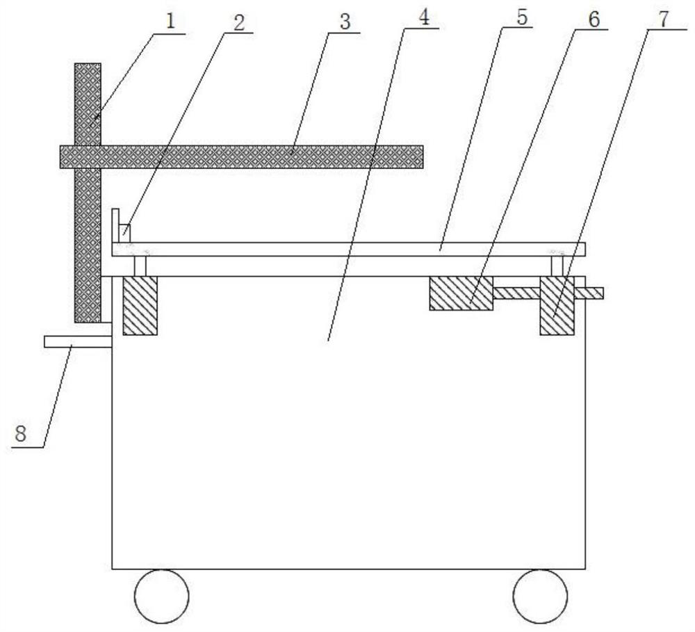
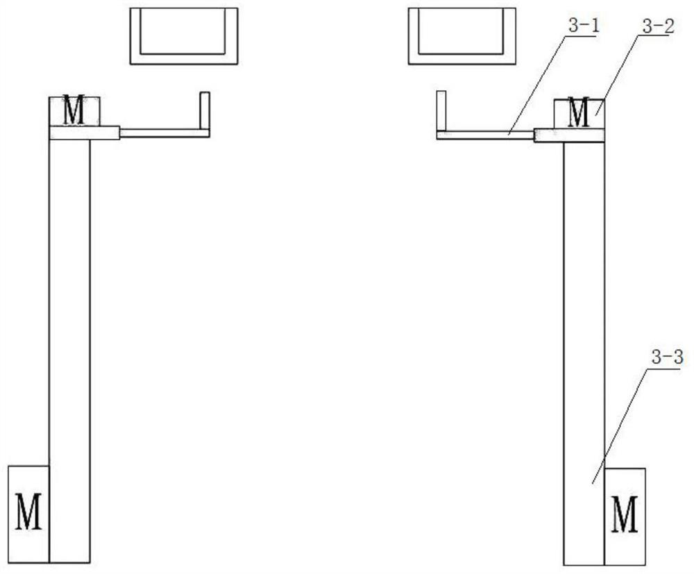
[0019] A 10kV-oriented semi-automatic switch trolley push-pull device, including a transfer vehicle 4, a platform 5, a mechanical arm 3 and an electric crank. Two handles 8 are symmetrically fixed on the side plate of the transfer vehicle, and two mechanical arm lifting mechanisms 1 are symmetrically fixed above the handle, and the two mechanical arm lifting mechanisms are respectively connected to two mechanical arms. Four platform elevating mechanisms 7 are fixed symmetrically at the four corners of the top of the transfer vehicle, and the four platform elevating mechanisms are fixed with the bottom surface of the platform to drive the platform to move up and down. A limit switch 2 is installed on one side of the platform close to the tran...


PUM


Abstract

The invention relates to a 10kV-oriented semi-automatic switch trolley push-and-pull device, which comprises a transfer trolley, a platform, mechanical arms and an electric crank, wherein two handlesare symmetrically and fixedly arranged on one side plate of the transfer trolley, two mechanical arm lifting mechanisms are symmetrically and fixedly arranged above the handles, and are connected withthe two mechanical arms respectively, and four platform lifting mechanisms are symmetrically and fixedly installed at the four corners of the top of the transfer trolley and fixedly installed on thebottom face of the platform to drive the platform to move up and down. According to the invention, the process of pushing and pulling the 10kV switch trolley by a worker is greatly simplified, and thelabor intensity of the worker is reduced.

Description

technical field [0001] The invention belongs to the field of power transformation operation, and relates to a 10kV switch trolley, in particular to a 10kV-oriented semi-automatic switch trolley push-pull device. Background technique [0002] At present, the change of the operating position and test position of the 10kV switch trolley in the substation requires manual operation with the hand crank. In the process of separating from the live bus, there is a hidden danger of discharge. [0003] There is an urgent need for an electrically operated crank that can reduce the working intensity of staff and increase work safety. [0004] In addition, the test position and maintenance position conversion of the trolley and transfer vehicle of the existing 10kV switchgear are also operated manually, and the degree of automation is not high. Contents of the invention [0005] The purpose of the present invention is to overcome the deficiencies of the prior art, and provide a semi-a...

Claims


Application Information

Patent Timeline
IPC IPC(8): H02B11/167H02B11/02H02B1/50
CPCH02B11/167H02B11/02H02B1/505
Inventor 王一品刘伟孙斌肖建超张建桐孔晓利
Owner STATE GRID TIANJIN ELECTRIC POWER
Features
  • R&D
  • Intellectual Property
  • Life Sciences
  • Materials
  • Tech Scout
  • Unparalleled Data Quality
  • Higher Quality Content
  • 60% Fewer Hallucinations
Learn More