
Fire-fighting lifting device for fire-fighting equipment

A fire-fighting equipment and lifting device technology, which is applied in fire rescue and other directions, can solve problems such as channel congestion, increased labor intensity, and unsafe operation, and achieve the effects of convenient movement, reduced labor intensity, and simple operation

Inactive Publication Date: 2021-02-05
湖南赤道技术开发有限公司
View PDF0 Cites 1 Cited by
  • Summary
  • Abstract
  • Description
  • Claims
  • Application Information

AI Technical Summary

Problems solved by technology

[0002] Fire-fighting equipment is an extremely important part of our daily life. It guarantees the safety of our lives and property to a certain extent. The passages in the area are too crowded, and it is inconvenient for fire vehicles to enter, which affects the rescue time. The fire can only be extinguished by firefighters holding the fire belt. However, the fire belt has a high water pressure and needs to be lifted for a long time, so it has a great impact on the physical strength of the firefighters. Moreover, sometimes a sufficient height is required, that is, the nozzle needs to be high enough to face the fire source. A common method is to use a tool so that firefighters stand on the tool to meet the height requirement, but this This method is unsafe to operate, and the high-pressure water gun will make the firefighters stand unsteadily, the effect is more dangerous, and the labor intensity will be greatly increased

Method used


Image

  • Fire-fighting lifting device for fire-fighting equipment
  • Fire-fighting lifting device for fire-fighting equipment
  • Fire-fighting lifting device for fire-fighting equipment

Examples


Embodiment 1

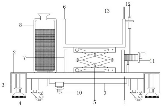
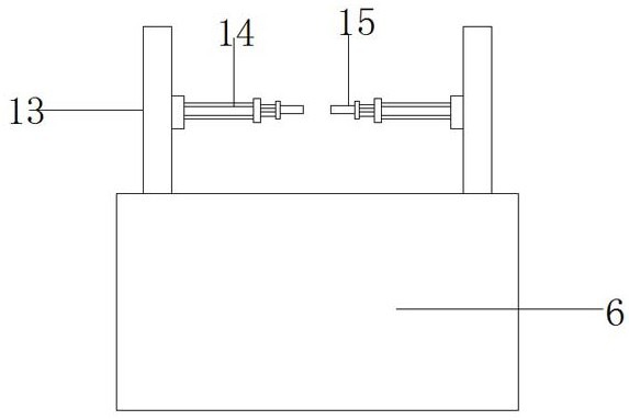
[0018] Embodiment 1, with reference to Figure 1-3 , a fire-fighting lifting device for fire-fighting equipment, including a base plate 1, an installation box 2 is welded on the outer walls of both sides of the base plate 1, and a hydraulic cylinder 3 is welded on the inner wall of the top of the installation box 2, and a support block 4 is welded at the end of the hydraulic cylinder 3 , the outer wall of the bottom of the support block 4 is welded with a non-slip mat, and the size of the anti-slip mat is compatible with the size of the support block 4, the outer wall of the top of the bottom plate 1 is welded with a lifting platform 5, and the top of the lifting platform 5 is welded with a support platform 6, supporting The platform 6 rises under the action of the lifting platform 5, and an appropriate height is selected according to the needs. At the same time, the supporting platform 6 protects the firefighters to prevent the firefighters from falling. The outer wall of the ...


PUM


Abstract

The invention discloses a fire-fighting lifting device for fire-fighting equipment. The fire-fighting lifting device for the fire-fighting equipment comprises a bottom plate, mounting boxes are weldedto the outer walls of the two sides of the bottom plate, hydraulic oil cylinders are welded to the inner walls of the tops of the mounting boxes, supporting blocks are welded to the tail ends of thehydraulic oil cylinders, a lifting table is welded to the outer wall of the top of the bottom plate, a supporting table is welded to the top of the lifting table, a protection groove is welded to theouter wall of the bottom plate, the protection groove is matched with the lifting table, a water tank is welded to the outer wall of the top of the bottom plate, a water pipe penetrating through the bottom plate is arranged at the bottom of the water tank and provided with a water pump, and a reel is rotatably connected to the outer wall of one side, away from the water tank, of the protection groove. In the fire-fighting lifting device for the fire-fighting equipment, the supporting table selects a proper height according to needs, a fire hose is wound and unwound through the reel, the properlength is selected according to needs, the fire-fighting lifting device is simple to operate, convenient to move and suitable for fire-fighting work in a multi-storey old residential area with a narrower passage, a fixing block carries out clamping and fixing on a fire-fighting faucet to offset recoil force of the fire-fighting faucet, and therefore the labor intensity of firefighters is reduced.

Description

technical field [0001] The invention relates to the technical field of fire-fighting equipment, in particular to a fire-fighting lifting device for fire-fighting equipment. Background technique [0002] Fire-fighting equipment is an extremely important part of our daily life. It guarantees the safety of our lives and property to a certain extent. The passages in the area are too crowded, and it is inconvenient for fire vehicles to enter, which affects the rescue time. The fire can only be extinguished by firefighters holding the fire belt. However, the fire belt has a high water pressure and needs to be lifted for a long time, so it has a great impact on the physical strength of the firefighters. Moreover, sometimes a sufficient height is required, that is, the nozzle needs to be high enough to face the fire source. A common method is to use a tool so that firefighters stand on the tool to meet the height requirement, but this This method is unsafe to operate, and the high-...

Claims


Application Information

Patent Timeline
Patent Type & Authority Applications(China)
IPC IPC(8): A62C31/00A62C31/28A62C33/04
CPCA62C31/00A62C31/28A62C33/04
Inventor 马丹
Owner 湖南赤道技术开发有限公司
Learn More