Independent air chamber jigger

An air chamber and jig technology, applied in the field of jigs, can solve the problems of reducing equipment reliability, affecting valves, affecting sorting effects, etc., and achieving the effects of reducing production costs, improving production efficiency, and saving water resources

Pending Publication Date: 2021-02-05
南通方驰机械有限公司
View PDF0 Cites 0 Cited by
  • Summary
  • Abstract
  • Description
  • Claims
  • Application Information

AI Technical Summary

Problems solved by technology

If the height of the air chamber is too small, the longitudinal wave height distribution of the sieve plate will be uneven, and the air pressure will be too high, and the air will burst out of the air chamber to destroy the bed layer; if the height of the air chamber is too high, the static pressure loss of the water flow will also increase, which will affect the stratification effect ;When the air chamber is exhausted for too long, the air chamber will be submerged or even the water will be discharged. Therefore, the common disadvantage of ordinary jigs is that there must be air and water in contact to form an interface between water and air, so that the air discharged through the exhaust valve Inevitably, there will be water, causing the air valve to spray water, affecting the action of the valve, reducing the reliability of the equipment, and at the same time, water leakage occurs, resulting in waste of water resources; in addition, when the equipment is large-scale, the horizontal pulsation in the jigging chamber Uneven water flow affects the sorting effect

Method used


Image

  • Independent air chamber jigger
  • Independent air chamber jigger
  • Independent air chamber jigger

Examples


Embodiment 1

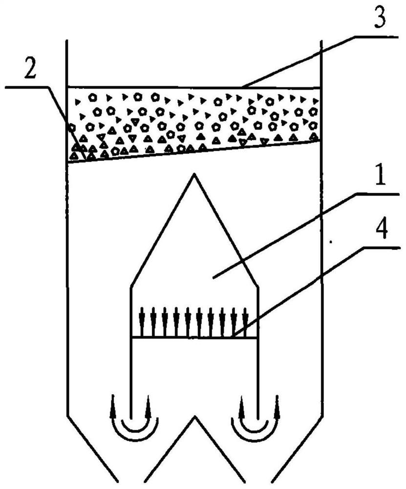
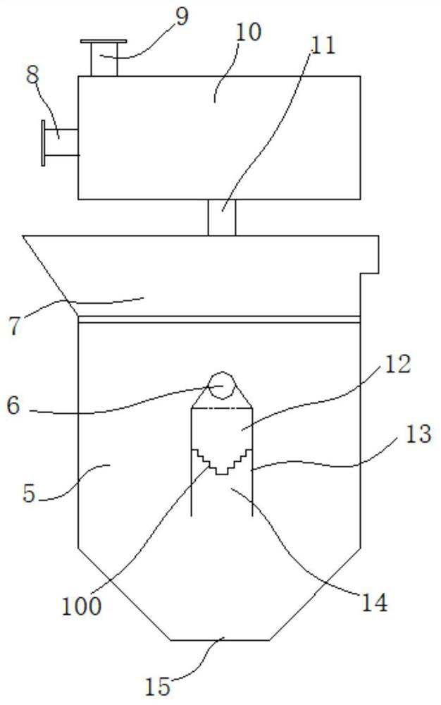
[0040] Such as image 3 with Figure 4 Shown, a kind of independent air chamber jigging machine comprises compressed air source, bellows 10 and the jigging chamber 5 that has screening groove 7 at the top;

[0041] The bellows 10 is provided with an air inlet end 8, an air outlet end 9 and an air supply end 11, an air inlet valve is arranged on the air inlet end 8, an air outlet valve is arranged on the air outlet end 9, and the compressed air source is connected to the air outlet through an air pipe. wind end 8;

[0042] The jigging chamber 5 is provided with a ventilation duct 6, one end of the ventilation duct 6 is blocked, and the other end extends out of the jigging chamber 5, and is connected to the air supply end 11 through the air duct;

[0043] A plurality of independent air chambers 13 are evenly distributed in the jigging chamber 5, each independent air chamber 13 is closed at the top and open at the bottom, and the independent air chamber 13 is provided with a de...

Embodiment 2

[0050] On the basis of Example 1, such as Figure 5 As shown, the bottom of the jigging chamber 5 has a sieve material discharge port 15, and the side wall of the jigging chamber 5 is provided with sorting impurities that are respectively connected to the sieve material discharge port 15 and the discharge end of the screening tank 7. Channel 17, the sorting impurity channel 17 is provided with a discharge device, and the screening tank 7 is provided with a bed thickness detection device, the bed thickness detection device and the discharge device are respectively electrically connected to the controller, and the controller obtains the bed thickness detection device. The bed thickness signal fed back by the device controls the operation of the discharge device, so that the sorted impurities in the jig chamber 5 are discharged through the sorted impurity channel 17 .

[0051] Preferably, the bed thickness detection device adopts a bed thickness sensor 16 .

[0052] Preferably, ...

Embodiment 3

[0055] On the basis of Example 2, such as Figure 6 As shown, a plurality of independent air chambers 13 are distributed side by side in at least two rows in the jigging chamber 5, and each row of independent air chambers 13 is respectively provided with a ventilation duct 6, and the independent air chambers 13 of the same row are connected in parallel to the corresponding ventilation ducts 6, Between the independent air chambers 13 of adjacent columns, a partition 19 whose lower end extends to the bottom of the jigging chamber 5 is arranged.

[0056] In this embodiment, the independent air chambers 13 of each column form a relatively independent jigging space through the partition plate 19, which avoids the mutual influence of the independent air chambers 13 of adjacent columns during the jigging process, and can ensure that the horizontal and vertical directions of the jigging machine are uniform. The pulsating water flow is conducive to the realization of large-scale equipm...


PUM


Abstract

The invention discloses an independent air chamber jigger which comprises a compressed air source, an air box and a jigging chamber with a screening groove in the top. An air inlet end, an air outletend and an air supply end are arranged on the air box, an air inlet valve is arranged at the air inlet end, an air outlet valve is arranged at the air outlet end, and the compressed air source is connected with the air inlet end through an air pipe. A ventilating pipeline is arranged in the jigging chamber, one end of the ventilating pipeline is blocked, and the other end of the ventilating pipeline extends out of the jigging chamber and is connected with the air supply end through an air pipe. A plurality of independent air chambers are further evenly distributed in the jigging chamber, the tops of the independent air chambers are closed, the bottoms of the independent air chambers are open, deformation diaphragms dividing the independent air chambers into inner air chambers and outer airchambers are arranged in the independent air chambers, and the inner air chambers are communicated with the ventilating pipeline in parallel. According to the independent air chamber jigger, no contact between air and water is realized, water is prevented from being discharged during exhaust to influence the action of the valves, the equipment reliability is improved, the water leakage phenomenonis avoided, the problem of non-uniform transverse pulsating water flow after the equipment is large-scale is solved, and the sorting effect is improved.

Description

technical field [0001] The invention relates to a jig, in particular to a jig with an independent air chamber. Background technique [0002] At present, jig machines used at home and abroad generally use fixed air chambers, which are divided into screen side air chambers, under-screen air chambers and compound air chambers. They all use the principle of U-shaped tubes. figure 1 The sieve side (side drum type) air chamber jig machine air exerts pulsating pressure from one side of the U-shaped pipe (air chamber side) on one side of the U-shaped pipe, and obtains pulsating rising water flow on the other side (jigging chamber side) , The rising water flow passes through the sieve plate agitating sieve, so that the materials on the sieve plate agitating sieve are loosened, so that the materials are layered according to the density, so as to achieve the purpose of separation. figure 2 The under-screen air chamber jig machine deforms the U-shaped tube, and the air chamber is inst...

Claims


Application Information

Patent Timeline
Patent Type & Authority Applications(China)
IPC IPC(8): B03B5/16B03B5/24
CPCB03B5/16B03B5/24
Inventor 倪建校
Owner 南通方驰机械有限公司
Why Eureka
Try Eureka