Anti-blocking rapid spraying equipment

A spray equipment and anti-clogging technology, applied in the direction of spray devices, etc., can solve the problems of glass tube burst, increase the cost of providing heat energy, damage to spray equipment, etc., so as to reduce the risk of freezing, improve the cleaning effect, and meet the fire protection requirements. Effect

Active Publication Date: 2021-02-05
浙江继望锻造科技有限公司
View PDF6 Cites 1 Cited by
  • Summary
  • Abstract
  • Description
  • Claims
  • Application Information

AI Technical Summary

Problems solved by technology

[0004] However, in the prior art, under winter conditions, the water inside the rapid sprinkler equipment is easy to freeze, and because the density of ice is lower than that of water, the frozen rapid sprinkler equipment will be subjected to a large expansion force, making the spray The glass tube inside the shower head is subject to high pressure, which may easily cause the glass tube to burst, which in turn will cause damage to the rapid spraying equipment. Due to the relatively dry winter climate and frequent fires, if the sprinkler head is damaged in extremely cold conditions, if it is not repaired in time Replacement will greatly increase the risk of fire protection and threaten the safety of people's lives and property. At the same time, the frozen fire water pipes will also prevent the normal spraying of fire water. By continuously flowing the heating fluid inside the pipeline, the winter heating of the fire-fighting water pipe can be realized, and the water inside the pipeline can be avoided from freezing. Poor, on the other hand, the heat is easily lost, which increases the cost of providing heat energy. At the same time, the inner wall of the fire water pipe after heating is easy to adhere to a large amount of water stains. If it is not cleaned for a long time, it is easy to cause half blockage or full blockage , affecting normal fire water safety and other issues

Method used


Image

  • Anti-blocking rapid spraying equipment
  • Anti-blocking rapid spraying equipment
  • Anti-blocking rapid spraying equipment

Examples


Embodiment approach

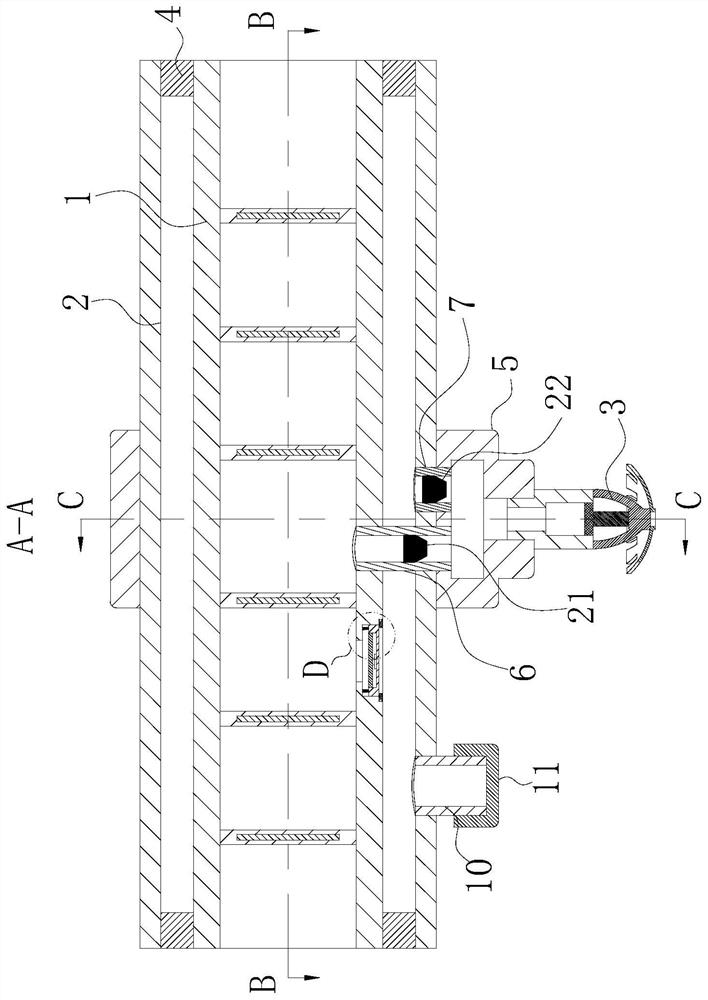
[0029] As an embodiment of the present invention, the inner conduit 1 is provided with limiting grooves near the opening below the adjustment hole; the number of the limiting grooves is two, and they are arranged symmetrically; the insides of the two limiting grooves are both The limit block 14 is slidingly connected, and the bottom of the limit groove is fixedly connected with the second electric telescopic rod 15, and the second electric telescopic rod 15 is fixedly connected with the corresponding limit block 14 respectively; during work, when When the inside of the inner conduit 1 is pressurized and desilted, in order to avoid pressurization, the water inside the inner conduit 1 presses the regulating block 8, so that the inner conduit 1 and the outer conduit 2 are directly connected, resulting in resistance inside the inner conduit 1. The stagnant matter enters the inside of the outer conduit 2, which affects the normal operation of the outer conduit 2. By setting the limi...


PUM


Abstract

The invention belongs to the technical field of fire-fighting equipment, and particularly relates to anti-blocking rapid spraying equipment which comprises an inner guide pipe, an outer guide pipe anda spraying head. The outer part of the inner guide pipe is sleeved with the outer guide pipe. A guide block is fixedly connected to the lower part in the outer guide pipe. The spraying head is arranged below the guide block. An adjusting hole is formed in the position, close to the spraying head, of the surface of the inner guide pipe. An adjusting block is connected to the interior of the adjusting hole in a sliding manner. Springs which are uniformly distributed are fixedly connected to the upper surface of the adjusting block. Through the equipment, isolation between a pipeline used by thespraying equipment and external environment is effectively achieved; through multi-layer structural design, the inner guide pipe is prevented from making direct contact with the external environment,the freezing risk of water in the inner guide pipe is reduced, and the problem that a transistor of the spraying head is extruded to burst is avoided; and meanwhile, through the adjusting block, theinner guide pipe and the outer guide pipe in a clogged state are directly communicated, so that the water spraying flow of the spraying head is ensured, and the fire-fighting requirement is met.

Description

technical field [0001] The invention belongs to the technical field of fire-fighting equipment, in particular to anti-clogging rapid spray equipment. Background technique [0002] The fire sprinkler is used in the fire sprinkler system. When a fire breaks out, the water is sprayed out through the sprinkler splash plate to extinguish the fire. It is divided into a pendant sprinkler, a vertical sprinkler, a common sprinkler, and a side wall sprinkler Nozzle etc. [0003] According to CN106249552B, a spraying device, the spraying device provided by the invention greatly improves the practicability and flexibility, facilitates equipment adjustment, failure analysis and engineering experiments, and at the same time greatly improves engineering efficiency and reduces poor spraying. The process yield rate is improved, and the production cost is reduced. [0004] However, in the prior art, under winter conditions, the water inside the rapid sprinkler equipment is easy to freeze, a...

Claims


Application Information

Patent Timeline
Patent Type & Authority Applications(China)
IPC IPC(8): B05B15/50
CPCB05B15/50
Inventor 马泽涛
Owner 浙江继望锻造科技有限公司
Why Eureka
Try Eureka