
Electric screwdriver special for electric energy meter verification

A technology for the verification of electric screwdrivers and electric energy meters, which is applied in the direction of motor tools and manufacturing tools, can solve the problems of inconsistent tightening degree of screws in the same row of electric energy meters and low efficiency of single-batch head screwdrivers, and achieves simple structure, consistent torque, and reduced The effect of low labor intensity

Pending Publication Date: 2021-02-05
LVLIANG POWER SUPPLY COMPANY STATE GRID SHANXI ELECTRIC POWER
View PDF0 Cites 2 Cited by
  • Summary
  • Abstract
  • Description
  • Claims
  • Application Information

AI Technical Summary

Problems solved by technology

[0003] The present invention overcomes the deficiencies of the prior art, and proposes a special electric screwdriver for electric energy meter verification, aiming at solving the problems of low efficiency of using a single-batch head screwdriver and inconsistent tightening degree of the same row of screws for the electric energy meter.

Method used


Image

  • Electric screwdriver special for electric energy meter verification

Examples


Embodiment 1

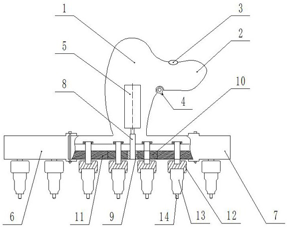
[0012] Example 1, such as figure 1 As shown, it is a special electric screwdriver for electric energy meter verification of the present invention, including a housing 1, a motor 5, an electric switch 4, a reversing switch 3, and a rotating rod 8. The lower part of the shaft of the motor 5 is fixedly connected with the rotating rod 8, and the electric switch 4 It is electrically connected with the motor 5 and is used to control the rotation or stop of the electric screwdriver. The reversing switch 3 is electrically connected with the motor 5 and is used to control the forward or reverse rotation of the electric screwdriver. The handle 2 is provided on the housing 1 for operation When convenient to hold, the lower end of the rotating rod 8 is connected with a driving gear 9 by a key, and the left and right sides of the driving gear 9 are symmetrically provided with the first gear 10 meshed with it, and the first gear 10 is set away from the side of the driving gear 9 The second ...

Embodiment 2

[0016] In embodiment 2, the second housing 6 and the third housing 7 are non-detachably connected to the housing 1, and other settings are the same as in embodiment 1, so that when in use, if only the single-phase meter is checked, the second The batch heads 14 in the second housing 6 and the third housing 7 are removed, and if the three-phase meter is to be checked, then the batch heads 14 in the second housing 6 and the third housing 7 are installed.

[0017] In the present invention, by setting four batch heads 14 or seven batch heads 14, a row of screws can be tightened or disassembled at the same time, and an electric screwdriver can be carried to complete the quick inspection of single-phase meters and three-phase meters, which improves work efficiency , by setting the idle screwdriver 13, the torque of the same row of screws can be guaranteed to be consistent; the operation is simple, and the staff can be familiar with and skillfully use it within a few minutes, reducing...


PUM


Abstract

The invention provides an electric screwdriver special for electric energy meter verification, and belongs to the technical field of screwdrivers. The electric screwdriver aims to solve the problems of low efficiency of using a single-bit screwdriver and inconsistent screwing degrees of screws in the same row of an electric energy meter during meter verification. According to the technical scheme,a driving gear is arranged at one end of a motor of the electric screwdriver in a sleeving manner, first gears meshed with the driving gear are symmetrically arranged at the two sides of the drivinggear, an electric screwdriver with four screwdriver bits and an electric screwdriver with seven screwdriver bits are integrated by arranging other gears meshed with the first gears, an idling type screwdriver is arranged between the screwdriver bits and the gears, and the torque consistency of bolts in the same row is realized; and the electric screwdriver has the technical effects that the structure and the operation are simple, one row of bolts can be screwed down or dismounted at the same time, the working efficiency is improved, the torque consistency of screws in the same row can be guaranteed, and the labor intensity of workers is reduced.

Description

technical field [0001] The invention belongs to the technical field of screwdrivers, in particular to an electric screwdriver specially used for electric energy meter verification. Background technique [0002] The single-phase watt-hour meter has 4 rows of screws facing each other, and the three-phase watt-hour meter has 7 rows of screws facing each other. At present, in the preparation work for meter inspection, it is necessary to tighten all the screws in the lower row, and screw the screws in the upper row until they are in line with the verification pins. A certain distance is enough. However, the traditional electric screwdriver has only one bit. When calibrating and installing the electric energy meter, only one screw can be tightened or disassembled at a time. The operation is time-consuming and laborious, and the work efficiency is low. , the degree of tightening is entirely controlled by humans, and it is difficult to ensure that the torque of the screws in the sam...

Claims


Application Information

Patent Timeline
Patent Type & Authority Applications(China)
IPC IPC(8): B25B21/00
CPCB25B21/00
Inventor 段淇文段志明郝秀聪张冬丽梁欢曹群闫红丽张宏琴
Owner LVLIANG POWER SUPPLY COMPANY STATE GRID SHANXI ELECTRIC POWER
Learn More