

Diameter-adjustable circular glass cutting machine
An adjustable, cutting machine technology, applied in the direction of stone processing tools, work accessories, manufacturing tools, etc., to achieve the effect of easy collection
- Summary
- Abstract
- Description
- Claims
- Application Information
AI Technical Summary
Problems solved by technology
Method used
Image

Examples
Embodiment 1
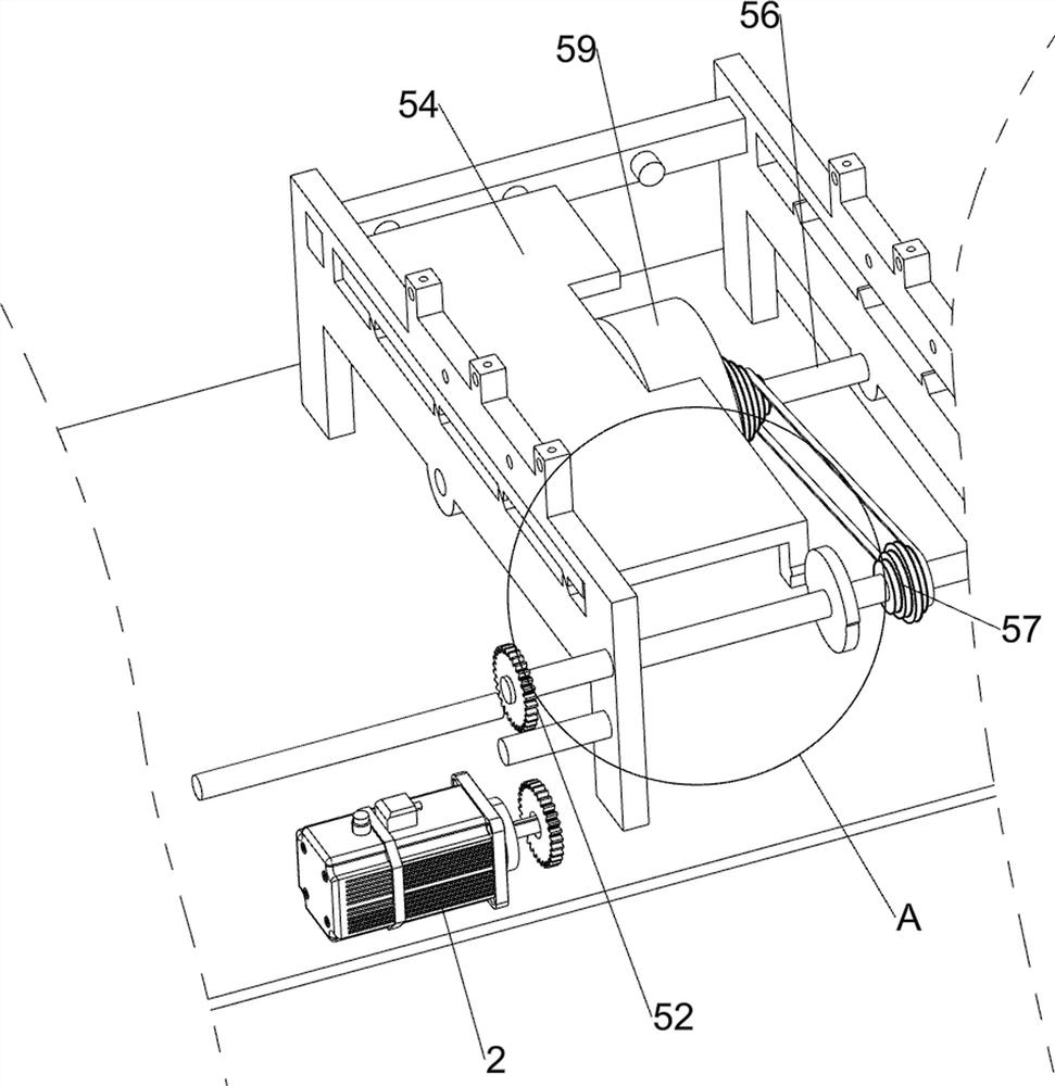
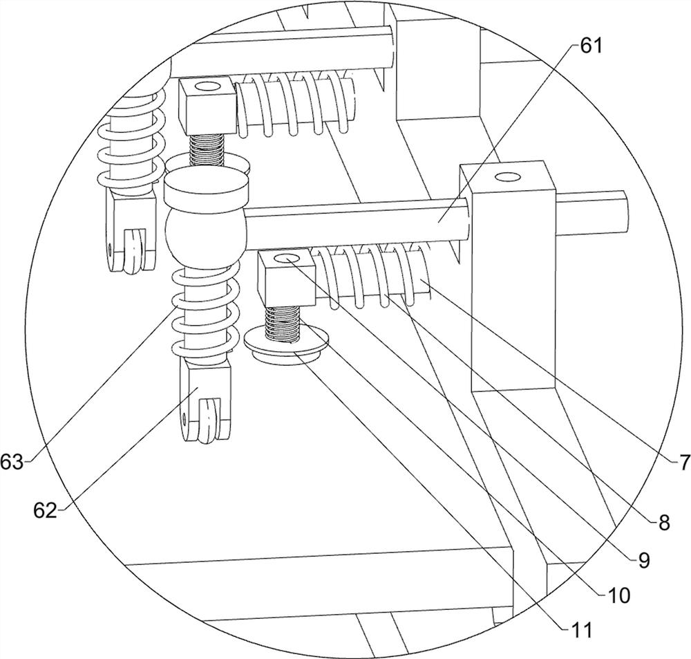
[0050] A circular glass cutter with adjustable diameter such as figure 1 and image 3 As shown, it includes a base 1, a first support platform 101, a second support platform 102, a servo motor 2, a transmission mechanism 3, a cutting mechanism 4 and a feeding mechanism 5, and the right side of the top of the base 1 is connected with the first support platform 101, the second A support platform 101 is connected with a feeding mechanism 5, the left side of the top of the base 1 is connected with a second support platform 102, the front side of the top of the base 1 is provided with a servo motor 2, the left side of the top of the base 1 is connected with a transmission mechanism 3, and the transmission mechanism 3 and The servo motor 2 is connected by transmission, and the cutting mechanism 4 is connected between the top of the second support platform 102 and the transmission mechanism 3 .
[0051] When the staff needs to cut the glass, the glass can be placed on the first supp...
Embodiment 2
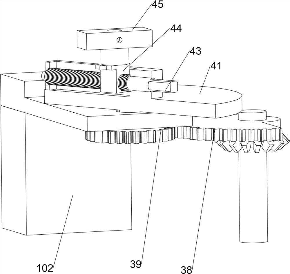
[0053] On the basis of Example 1, such as Figure 2 to Figure 6As shown, the transmission mechanism 3 includes a bearing seat 31, a first rotating shaft 32, a first gear 33, a second rotating shaft 34, a first bevel gear set 35, a second bevel gear set 36, a third rotating shaft 37, a sector gear 38 and For the second gear 39, two bearing seats 31 are arranged on the front side of the top of the base 1, and the bearing seats 31 are all located at the rear side of the servo motor 2, and the two bearing seats 31 are placed at right angles, and the front bearing seats 31 are connected with Rotating shaft 32, the first rotating shaft 32 right side and the servo motor 2 right side are all connected with the first gear 33, the rear side bearing block 31 is connected with the second rotating shaft 34, the front side of the second rotating shaft 34 and the first rotating shaft 32 left sides A first bevel gear set 35 is connected between them, a third rotating shaft 37 is connected to ...
PUM
 Abstract
Description
Claims
Application Information