Inkjet printing head mechanism, inkjet printing equipment, and ink droplet ejection angle correction method
An inkjet print head and inkjet head technology, applied in printing and other directions, can solve problems such as color mixing, uneven display, and position deviation of landing points, and achieve the effects of high resolution, improved precision, and improved stability
- Summary
- Abstract
- Description
- Claims
- Application Information
AI Technical Summary
Problems solved by technology
Method used
Image
Examples
Embodiment 1
[0046] This embodiment provides an inkjet printing head mechanism.
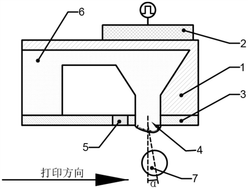
[0047] A kind of inkjet printing head mechanism, see image 3 As shown, it includes an inkjet head 1 , a piezoelectric component 2 and a temperature control 5 .
[0048]The inkjet head 1 has an inkjet cavity for containing ink 6 and nozzles 4 communicating with the inkjet cavity. There are multiple nozzles 4 , and each nozzle 4 is correspondingly provided with a temperature control 5 . The diameter of the nozzles 4 is not greater than 30 μm, and the distance between adjacent nozzles 4 is not less than 140 μm.
[0049] The piezoelectric component 2 is connected to the inkjet head 1 .
[0050] The temperature control 5 is disposed on the inkjet head 1 and close to the nozzles 4 . The temperature control 5 is arranged at the position directly behind the nozzle 4 along the printing direction, such as Figure 5 As shown, it should be noted that the printing direction is the direction of relative movement betw...
Embodiment 2
[0057] This embodiment provides an inkjet printing device.
[0058] An inkjet printing device includes a main body of the printing equipment and the inkjet printing head mechanism of Embodiment 1, and the inkjet printing head mechanism is installed on the main body of the printing equipment.
Embodiment 3
[0060] This embodiment provides a method for adjusting the exit angle of ink droplets.
[0061] A method for adjusting an ink droplet exit angle, comprising the steps of:
[0062] S1, the nozzle 4 of the inkjet head 1 ejects ink, and measures the initial exit angle α of the ink drop 7, as image 3 shown.
[0063] S2. Heat up or cool down the front end position or the rear end position of the nozzle 4 along the printing direction to form a temperature difference between the front end position and the rear end position of the nozzle 4 along the printing direction, and measure the ink corresponding to each temperature value Droplet exit angle, draw a graph for each temperature value and the corresponding ink droplet exit angle, and fit the graph.
[0064] S3. Calculate the temperature value to be set for the temperature control 5 corresponding to the deflection angle to be adjusted according to the graph.
PUM
 Abstract
Description
Claims
Application Information
 - R&D
- Intellectual Property
- Life Sciences
- Materials
- Tech Scout
- Unparalleled Data Quality
- Higher Quality Content
- 60% Fewer Hallucinations
Browse by: Latest US Patents, China's latest patents, Technical Efficacy Thesaurus, Application Domain, Technology Topic, Popular Technical Reports.
© 2025 PatSnap. All rights reserved.Legal|Privacy policy|Modern Slavery Act Transparency Statement|Sitemap|About US| Contact US: help@patsnap.com


