Eureka AIR delivers breakthrough ideas for toughest innovation challenges, trusted by R&D personnel around the world.

Hypersonic aircraft thermal structure scheme capable of improving aerodynamic efficiency

A hypersonic and aerodynamic efficiency technology, applied in the field of aircraft aerodynamics, can solve the problem of aircraft aerodynamic efficiency deviating from the predicted level, and achieve the effects of increasing the overall lift-to-drag ratio, total lift, and pressure difference

Active Publication Date: 2021-02-05
BEIHANG UNIV
View PDF6 Cites 0 Cited by
  • Summary
  • Abstract
  • Description
  • Claims
  • Application Information

AI Technical Summary

Problems solved by technology

For a hypersonic vehicle, changes in the aerodynamic shape will also lead to changes in the shock angle, which may cause the aerodynamic efficiency of the vehicle to deviate from the predicted level at the time of design

Method used


Image

  • Hypersonic aircraft thermal structure scheme capable of improving aerodynamic efficiency
  • Hypersonic aircraft thermal structure scheme capable of improving aerodynamic efficiency
  • Hypersonic aircraft thermal structure scheme capable of improving aerodynamic efficiency

Examples


Embodiment 1

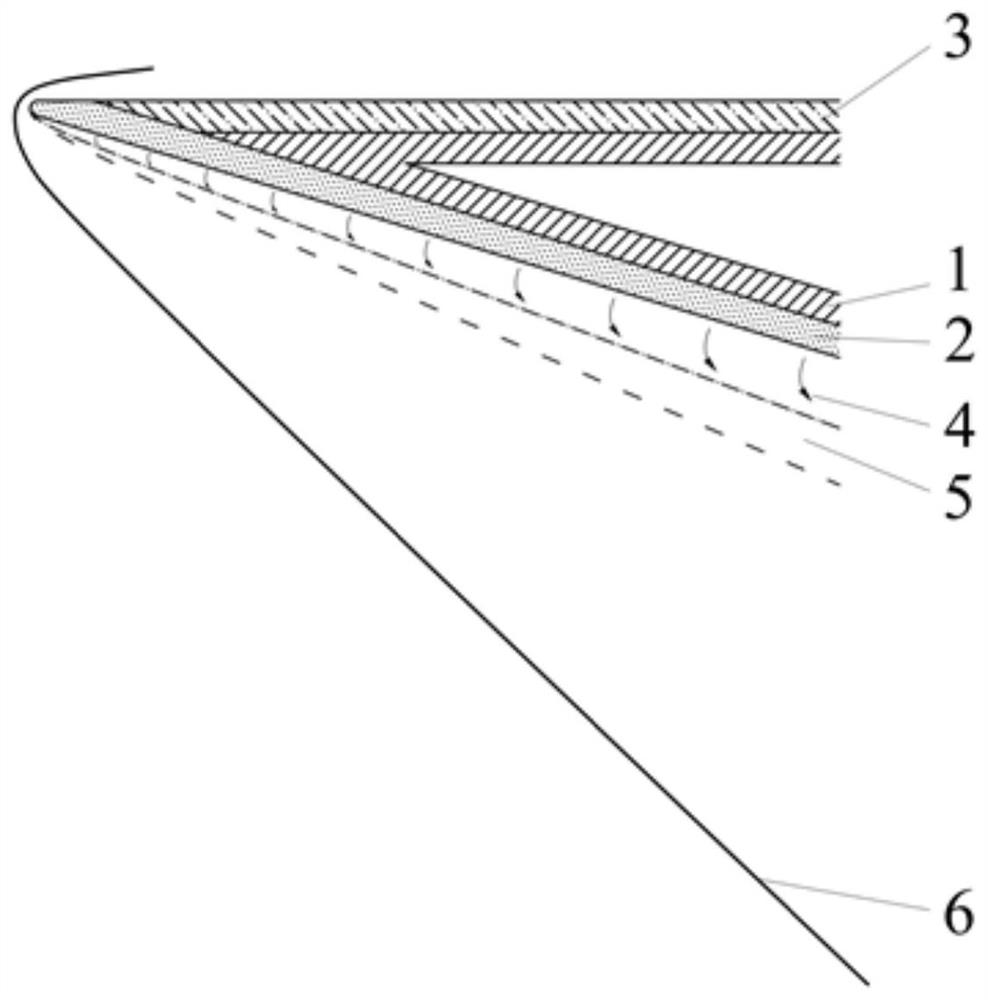
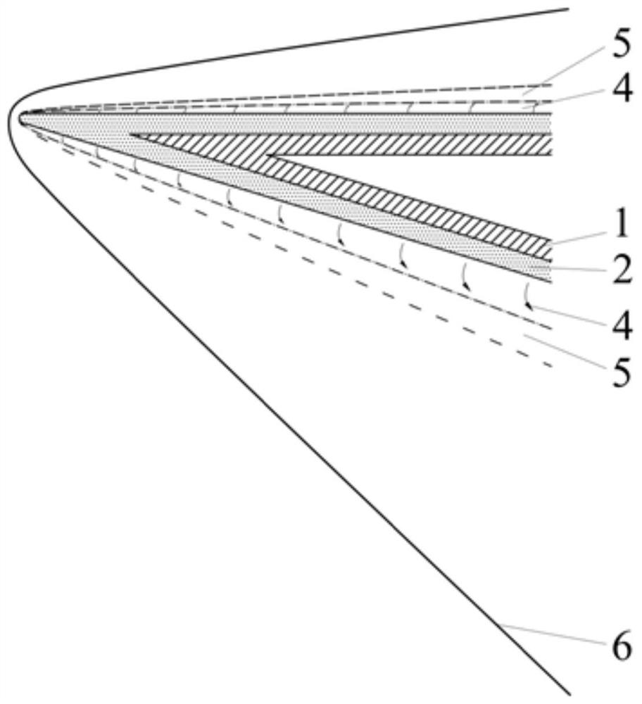
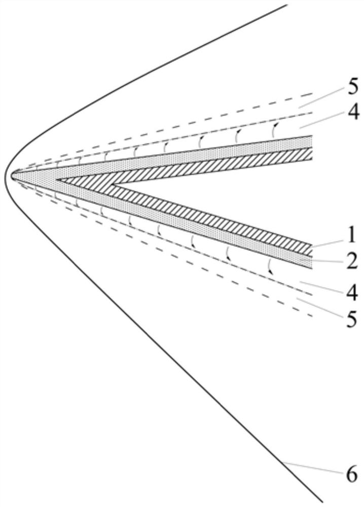
[0021] Such as figure 1 As shown, the lower wall of the aircraft shell 1 is coated with a phenolic resin material 2, and the upper wall of the aircraft shell 1 is coated with a heat insulating material 3 that will not generate gas when heated, the object plane angle of the upper wall is zero, and the lower wall The object plane angle of is not zero. The phenolic resin material 2 on the lower wall is heated to form an air cushion 4, and the air cushion 4 forms a flow shear layer 5 with the high-speed airflow. The equivalent surface angle of the lower wall increases, and the shock angle of the shock wave 6 increases accordingly, and the wave Afterwards, the pressure increases; and the upper wall will not form an air cushion, and the phenomenon of pressure increase will not occur. Therefore, the pressure difference between the upper and lower sides of the aircraft will increase, and the total lift of the aircraft will increase. Furthermore, the air cushion 4 formed on the lower ...


PUM


Abstract

According to a hypersonic aircraft thermal structure scheme capable of improving the aerodynamic efficiency, phenolic resin materials are arranged on the surface, namely the lower wall surface of an aircraft shell, which has a positive effect on lifting force, and phenolic resin materials are not arranged on the surface, namely the upper wall surface of the aircraft shell, which has a negative effect on the lifting force any more, other thermal insulation materials which do not generate gas when heated are used; in this way, the shock wave angle of the lower wall face of the aircraft shell canbe increased through the air cushion made of the phenolic resin materials, the pressure intensity of the lower wall face is increased accordingly, the pressure intensity cannot be increased due to the fact that the air cushion is formed on the upper wall face, and therefore the difference between the upper pressure intensity and the lower pressure intensity of the aircraft is increased, and the total lift force of the aircraft is increased. Moreover, the air cushion generated by the phenolic resin material on the lower wall surface can also reduce the frictional resistance, so that the overall resistance of the aircraft is reduced, and the overall lift-drag ratio of the aircraft is improved.

Description

technical field [0001] The invention relates to the technical field of aircraft aerodynamics, in particular to a thermal structure scheme for a hypersonic aircraft that can improve aerodynamic efficiency. Background technique [0002] Hypersonic refers to flight speeds above Mach 5. When the flight speed of the aircraft reaches hypersonic speed, the heat flow on its surface will reach a level that conventional materials cannot bear under the influence of aerodynamic heating phenomenon. Therefore, hypersonic vehicles require the use of heat-resistant composite materials in surface areas with higher heat flux. The heat-resistant composite materials with a long history are phenolic resin materials, which are mainly used for the inner surfaces of missiles, space shuttles and rocket engines. Phenolic resin materials can be cracked under the influence of high temperature to generate gas to take away a lot of heat, so as to prevent the heat flow from damaging the internal equipme...

Claims


Application Information

Patent Timeline
Patent Type & Authority Applications(China)
IPC IPC(8): B64C1/00B64C1/40B64C30/00
CPCB64C1/0009B64C1/40B64C30/00
Inventor 蒋崇文胡姝瑶李志豪何新高振勋李椿萱
Owner BEIHANG UNIV
Why Eureka
Eureka Blog
Learn More