
Novel protective structure of medical cold chain equipment

A protective structure and cold chain technology, which is applied to the types of packaging items, impact-sensitive items, and containers to prevent mechanical damage, etc. It can solve problems such as cold chain box drug damage, cold chain box misalignment and sliding, cold chain box displacement collision, etc. , to achieve the effect of improving the safety of use, improving the stability of stacking, and avoiding collision damage

Inactive Publication Date: 2021-02-05
西安思明制冷设备工程有限公司
View PDF3 Cites 1 Cited by
  • Summary
  • Abstract
  • Description
  • Claims
  • Application Information

AI Technical Summary

Problems solved by technology

[0008] The purpose of the present invention is to solve the problem that there is no function of positioning and stacking stacked cold chain boxes in the prior art, resulting in misplaced stacking, affecting the stability during transportation, and stacking due to sudden braking inertia and other reasons. The misalignment and sliding phenomenon of the adjacent cold chain boxes not only easily affects the stability of stacking, but also causes large displacement collisions of the cold chain boxes, which will seriously lead to the problem of damage to the cold chain boxes and the medicines inside them, and the proposed A new type of protective structure for medical cold chain equipment

Method used


Image

  • Novel protective structure of medical cold chain equipment
  • Novel protective structure of medical cold chain equipment
  • Novel protective structure of medical cold chain equipment

Examples


Embodiment 1

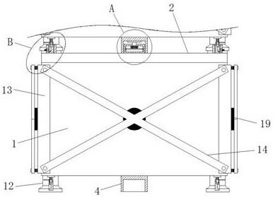
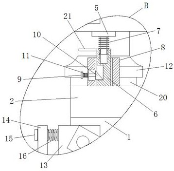
[0025] Example 1 as Figure 1-3 As shown, the protective structure of this new type of medical cold chain equipment includes a cold chain box body 1 and a box cover 2, and the rear side wall of the box cover 2 is rotatably connected to the rear upper edge of the cold chain box body 1 through a hinge. The upper end of the case cover 2 is fixedly connected with a positioning block 3, and the lower end of the cold chain box body 1 is fixedly connected with a positioning block 4, and the lower end of the positioning block 4 is provided with a positioning slot matching the positioning block 3, and the cold chain box body 1 is fixedly connected with a positioning block 4. The left and right sides of the lower end of the chain box body 1 are fixedly connected with T-shaped fixed rods 5, and the bottoms of the two T-shaped fixed rods 5 are provided with inserting rods 6, and the upper ends of the two inserted rods 6 are provided with T-shaped fixed rods. 5 matching chute, the first sp...

Embodiment 2

[0026] Embodiment 2 is on the basis of embodiment 1 such as figure 1 As shown, the corners of the four vertical parts of its cold chain box body 1 are fixedly connected with right-angle guards 13, and the four vertical side walls of the cold chain box body 1 are all provided with X-shaped anti-collision plates 14. , the upper and lower ends of the side walls of the four right-angled guard plates 13 away from the cold chain box body 1 are fixedly connected with T-shaped connecting rods 15, and the rod walls of the four T-shaped connecting rods 15 on the same side are all connected to each other through round holes. The left and right sides of the upper and lower ends of the side wall of the X-shaped anti-collision plate 14 on the same side are slidingly connected, and the rod wall of each T-shaped connecting rod 15 is movably sleeved with a third spring 16, and the four third springs 16 on the same side are respectively It is fixed between the side wall of the X-shaped anti-col...

Embodiment 3

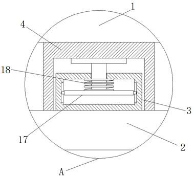
[0027] Embodiment 3 is such as on the basis of embodiment 1 figure 2As shown, the inside of its positioning block 3 is provided with a cavity, and the upper side wall of the cavity is slidably connected with the I-shaped bar 17 through the second slide hole, and the lower side horizontal part upper end of the I-shaped bar 17 is connected with the upper end of the cavity. The fourth spring 18 is fixedly arranged between the upper side walls, and the fourth spring 18 is movably socketed with the vertical part bar wall of the I-shape bar 17, and the positioning clamp 4 squeezes the I-shape bar 17 to a certain extent. There will be a certain vibration during transportation, and under the action of the fourth spring 18, the vibration generated during transportation can be offset to a certain extent, thereby reducing the impact of vibration on the cold chain box body 1.


PUM


Abstract

The invention relates to the technical field of cold chain equipment, and discloses a novel protective structure of medical cold chain equipment. The novel protective structure comprises a cold chainbox body and a box cover, the rear side wall of the box cover is rotatably connected with the edge of the upper end of the rear side of the cold chain box body through a hinge, the upper end of the box cover is fixedly connected with a positioning clamping block, a positioning clamping plate is fixedly connected to the lower end of the cold chain box body, a positioning clamping groove matched with the positioning clamping block is formed in the lower end of the positioning clamping plate, T-shaped fixing rods are fixedly connected to the left side and the right side of the lower end of the cold chain box body correspondingly, and inserting rods are arranged below the two T-shaped fixing rods correspondingly. By means of the novel protective structure of the medical cold chain equipment, positioning and stacking can be conducted during stacking, the stacking uniformity and stacking stability are improved, meanwhile, the situation that two adjacent cold chain boxes move in a staggered mode due to emergency brake inertia during transportation can be prevented, collision damage to the cold chain boxes and objects in the cold chain boxes due to large displacement is avoided, and the anti-collision performance of the cold chain boxes can be improved.

Description

technical field [0001] The invention relates to the technical field of cold chain equipment, in particular to a novel protective structure for medical cold chain equipment. Background technique [0002] The cold chain refers to certain food raw materials, processed food or semi-finished products, special biological products and pharmaceuticals after they are purchased, processed, sterilized and inactivated, during the process of product processing, storage, transportation, distribution, retail and use. , its various links are always in the specific low-temperature environment necessary for the product, reducing loss, preventing pollution and deterioration, and ensuring the special supply chain system of product food safety, biological safety, and drug safety. [0003] After searching, the Chinese patent publication number is CN206494338U, which discloses a cold chain transport box used in the medical field, including: a box body, a box cover, and a cover plate matched with t...

Claims


Application Information

Patent Timeline
Patent Type & Authority Applications(China)
IPC IPC(8): B65D81/18B65D6/34B65D81/07B65D25/24
CPCB65D7/44B65D25/24B65D81/07B65D81/18
Inventor 王挺锋
Owner 西安思明制冷设备工程有限公司
Learn More