Multi-functional embroidery machine and embroidery method thereof

An embroidery machine and multi-functional technology, applied in the field of embroidery machines, can solve the problems of not being able to tighten, not being able to embroider on fabrics, etc.

Inactive Publication Date: 2021-02-05
张秋菊
View PDF5 Cites 0 Cited by
  • Summary
  • Abstract
  • Description
  • Claims
  • Application Information

AI Technical Summary

Problems solved by technology

[0002] The invention with the publication number CN108611775A discloses an embroidery machine, which includes a workbench, an embroidery component, an X-axis moving device and a Y-axis moving device, wherein the workbench is used to fix the embroidery frame; the embroidery component is arranged on the workbench; The device is used to drive the embroidery frame or embroidery components to reciprocate along the X-axis direction, and the Y-axis moving device is used to drive the embroidery frame or embroidery components to reciprocate along the Y-axis direction; The mutual cooperation of the embroidery component and the embroidery frame on the workbench moves relative to the other along the X-axis and Y-axis in the horizontal plane, so that the movement of the embroidery component is more flexible and can reach the X-axis and Y-axis Any point in the plane coordinate system formed is not easy to form a dead angle, and the embroidery area is larger, which helps to improve the quality and efficiency of embroidery; but this embroidery machine cannot tighten the fabric and embroider the reverse side of the fabric

Method used


Image

  • Multi-functional embroidery machine and embroidery method thereof
  • Multi-functional embroidery machine and embroidery method thereof
  • Multi-functional embroidery machine and embroidery method thereof

Examples


specific Embodiment approach 1

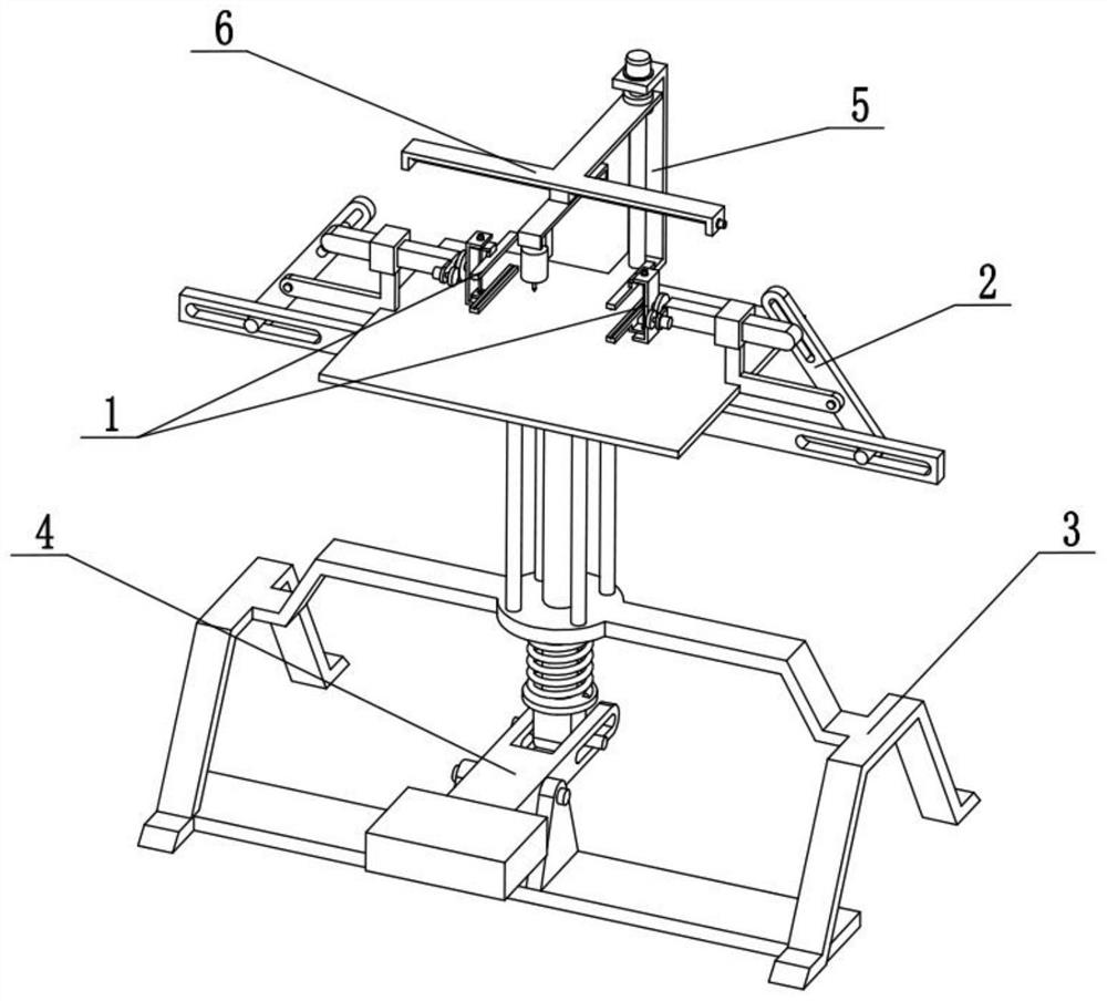
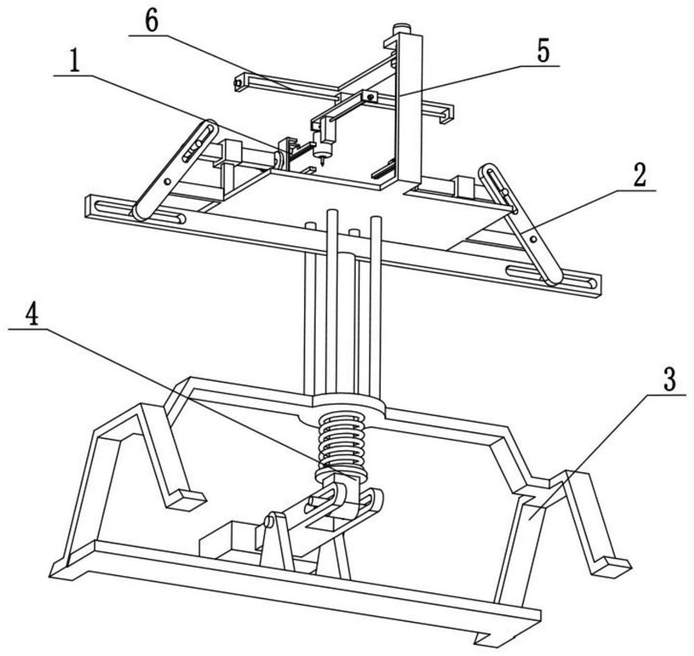
[0031] Combine below Figure 1-8 To illustrate this embodiment, the present invention relates to the technical field of embroidery machines, more specifically, a multi-functional embroidery machine, which includes a fabric clamping assembly 1, a fabric tensioning assembly 2, an integral frame assembly 3, and a pedal linkage assembly. 4. The height adjustment assembly 5 and the web moving assembly 6, the web moving assembly 6 is connected to the height adjustment assembly 5, the height adjustment assembly 5 is connected to the overall frame assembly 3, two fabric clips Tightening assembly 1 is respectively connected to two fabric tensioning assemblies 2, and two fabric tensioning assemblies 2 are respectively connected to the left and right ends of the overall frame assembly 3, and foot pedal linkage assembly 4 is connected to the overall frame assembly 3, two fabric tensioning assemblies 2 are respectively connected to the left and right ends of the pedal linkage assembly 4. ...

specific Embodiment approach 2

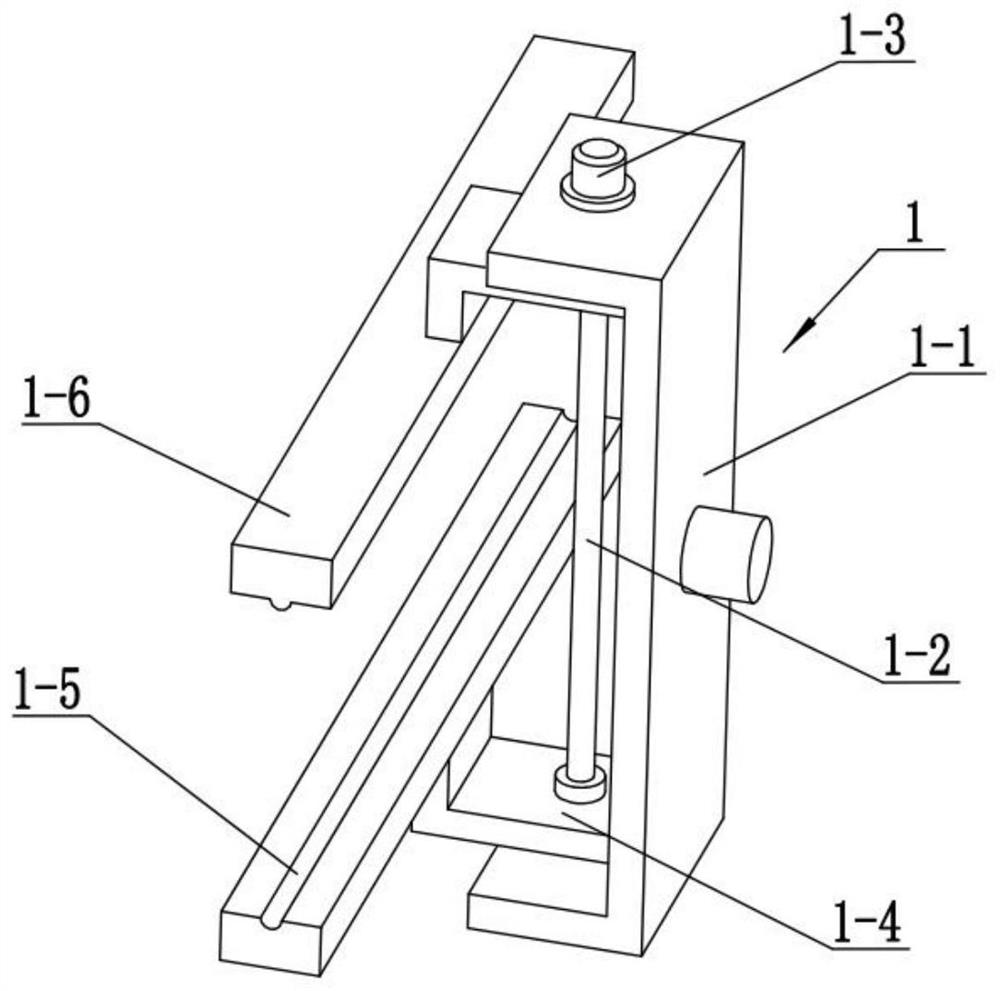
[0034] Combine below Figure 1-8Describe this embodiment, this embodiment will further explain the first embodiment, the cloth clamping assembly 1 includes a vertical slide 1-1, a clamping screw 1-2, a clamping motor 1-3, a clamping force Arm 1-4, groove base plate 1-5 and bump cover plate 1-6, groove base plate 1-5 and bump cover plate 1-6 are fixedly connected on two clamping force arms 1-4 respectively, two Two clamping arms 1-4 are respectively threaded on the upper and lower sides of the clamping screw rod 1-2, and the clamping screw rod 1-2 is rotatably connected to the vertical slide plate 1-1, and the clamping screw rod 1-2 Fixedly connected to the output shaft of the clamping motor 1-3, the clamping motor 1-3 is fixedly connected to the vertical slide 1-1, and both clamping arms 1-4 are slidingly connected to the vertical slide 1-1 superior.

[0035] The clamping motor 1-3 drives the clamping screw rod 1-2 to rotate, and the clamping screw rod 1-2 will drive the two...

specific Embodiment approach 3

[0037] Combine below Figure 1-8 Describe this embodiment, this embodiment will further explain the second embodiment, the fabric tensioning assembly 2 includes a right-angle arm 2-1, a horizontal sliding sleeve 2-2, a push-pull rod 2-3, a push-pull slideway 2- 4. Tighten slide bar 2-5, gear 2-6, overturn motor 2-7 and drive gear 2-8, drive gear 2-8 is fixedly connected on the output shaft of overturn motor 2-7, overturn motor 2-7 Fixedly connected on the tensioning slide bar 2-5, the tensioning slide bar 2-5 is slidably connected in the horizontal sliding sleeve 2-2, the horizontal sliding sleeve 2-2 is fixedly connected on the right-angle arm 2-1, and the push-pull rod 2- 3 Rotationally connected to the right-angle arm 2-1, the push-pull rod 2-3 is provided with a push-pull slideway 2-4, the tensioned slide rod 2-5 is slidably connected to the push-pull slideway 2-4, and the gear 2-6 is rotatably connected On the tensioning slide bar 2-5, the gear 2-6 is meshed with the dri...


PUM


Abstract

The invention relates to the technical field of embroidery machines, in particular to a multi-functional embroidery machine and an embroidery method thereof, which can tighten cloth and carry out embroidery on the reverse side of the cloth at the same time. The multi-functional embroidery machine comprises a cloth clamping assembly, a cloth tightening assembly, an integral frame assembly, a foot stepping linkage assembly, a height adjusting assembly and a breadth moving assembly. The method comprises the following steps: 1, stepping on a pedal plate with a foot, thus allowing a groove bottom plate and a convex block cover plate at the left end to be close to a groove bottom plate and a convex block cover plate at the right end; 2, flatly laying two ends of cloth between the groove bottom plates and the convex block cover plates on the same sides correspondingly, driving the groove bottom plates and the convex block cover plates on the same sides by two clamping motors to get close to clamp the two ends of the cloth correspondingly, loosening the pedal plate, and thus enabling two tightening sliding rods to get away from each other to tighten the cloth; and 3, after the embroidery machine finishes embroidery on the front surface, simultaneously driving two vertical sliding plates by two turnover motors to rotate in the same direction, driving the cloth to turn over through the two pairs of groove bottom plates and convex block cover plates, and thus enabling the back surface of the cloth to be upward.

Description

technical field [0001] The invention relates to the technical field of embroidery machines, in particular to a multifunctional embroidery machine and an embroidery method thereof. Background technique [0002] The invention with the publication number CN108611775A discloses an embroidery machine, which includes a workbench, an embroidery component, an X-axis moving device and a Y-axis moving device, wherein the workbench is used to fix the embroidery frame; the embroidery component is arranged on the workbench; The device is used to drive the embroidery frame or embroidery components to reciprocate along the X-axis direction, and the Y-axis moving device is used to drive the embroidery frame or embroidery components to reciprocate along the Y-axis direction; The mutual cooperation of the embroidery component and the embroidery frame on the workbench moves relative to the other along the X-axis and Y-axis in the horizontal plane, so that the movement of the embroidery compone...

Claims


Application Information

Patent Timeline
Patent Type & Authority Applications(China)
IPC IPC(8): D05C9/04D05C13/00
CPCD05C9/04D05C13/00
Inventor 张秋菊
Owner 张秋菊
Why Eureka
Try Eureka