Fireproof door

A fire door and door panel technology is applied in the field of fire doors to achieve the effect of speeding up evacuation and avoiding burns

Inactive Publication Date: 2021-02-05
梁春华
View PDF1 Cites 3 Cited by
  • Summary
  • Abstract
  • Description
  • Claims
  • Application Information

AI Technical Summary

Problems solved by technology

[0002] For example, the door frame described in publication number CN207879199U is hinged with a fire door body, the interior of the fire door body is the skeleton inner core of the steel structure net, the top of the door frame is fixedly connected with a top box, and the inside of the top box is A fire-proof sandbox is provided, and the fire-proof sandbox is provided with an opening on the bottom surface, and a blocked split gate is provided on the bottom of the fire-proof sandbox. At the end of the telescopic rod, the hydraulic push rod is fixed on the outer walls of both sides of the top box through the connecting plate; the disadvantage of this invention is that the door cannot be opened and closed with the foot when the door is overheated

Method used


Image

  • Fireproof door
  • Fireproof door
  • Fireproof door

Examples


specific Embodiment approach 1

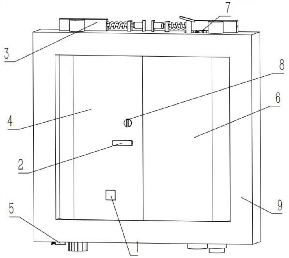
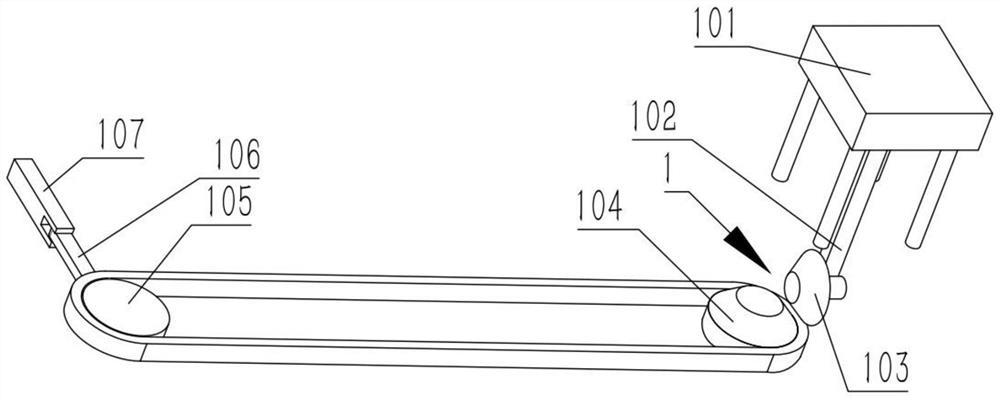
[0033] Combine below Figure 1-11 Describe this embodiment, a fire door, including a stepping mechanism 1 and a door lock mechanism 2, the stepping mechanism 1 includes a pedal 101, a stepping rack 102, a transmission gear 103, a bevel gear 104, a pulley 105, and a rotating rod 106 And slide bar 107, stepping on rack 102 is fixedly connected on pedal 101, stepping on rack 102 and transmission gear 103 engagement transmission, transmission gear 103 and bevel gear 104 engagement transmission, bevel gear 104 and belt pulley 105 belt transmission, rotating bar 106 is rotatably connected on the belt pulley 105, and the rotating rod 106 is rotatably connected on the slide bar 107. The door lock mechanism 2 includes a locking block 201 and a grooved slide bar 202, and the grooved slide bar 202 is fixedly connected on the locking block 201, and the slide bar 107 Fixedly connected on the grooved slide bar 202;

[0034]This device can prevent the fire from spreading after the fire deve...

specific Embodiment approach 2

[0036] Combine below Figure 1-11 Describe this embodiment, this embodiment will further explain Embodiment 1, the collection mechanism 2 also includes a cam 203, a rotating shaft 204, a door handle 205 and a door lock spring 206, the cam 203 is fixedly connected to the rotating shaft 204, and the rotating shaft Both left and right ends of 204 are fixedly connected with door handle 205, door lock spring 206 is fixedly connected on the slide bar 202 with groove, and slide bar 202 with groove is slidably connected on the cam 203 and the rotating shaft 204;

[0037] The door lock spring 206 pushes the grooved slide bar 202 to move due to the elastic force, and the grooved slide bar 202 moves to drive the locking block 201 to move, and the rotation of the door handle 205 drives the rotation shaft 204 to rotate, and the rotation of the rotation shaft 204 drives the rotation of the cam 203, and the rotation of the cam 203 drives the belt The grooved sliding rod 202 moves, and the gr...

specific Embodiment approach 3

[0039] Combine below Figure 1-11 Describe this embodiment mode, this embodiment mode will further explain Embodiment 2, the fire door also includes a reset mechanism 3, the reset mechanism 3 includes a reset rack 301, a reset spring 302, a deceleration piston rod 303 and a piston rod sleeve 304 , the reset spring 302 is fixedly connected to the reset rack 301 , the deceleration piston rod 303 is fixedly connected to the reset rack 301 , and the deceleration piston rod 303 is slidably connected in the piston rod sleeve 304 .


PUM


Abstract

The invention relates to the technical field of fireproof doors, in particular to a fireproof door. The fireproof door comprises a treading mechanism and a door lock mechanism, the treading mechanismcomprises a pedal, a treading rack, a transmission gear, a bevel gear, a belt wheel, a rotating rod and a sliding rod, the treading rack is fixedly connected to the pedal, the treading rack and the transmission gear are in meshing transmission, the transmission gear is in meshing transmission with the bevel gear, the bevel gear is in belt transmission with the belt wheel, the rotating rod is rotatably connected to the belt wheel, the rotating rod is rotatably connected to the sliding rod, the door lock mechanism comprises a locking block and a grooved sliding rod, the grooved sliding rod is fixedly connected to the locking block, and the sliding rod is fixedly connected to the grooved sliding rod.

Description

technical field [0001] The invention relates to the technical field of fire doors, in particular to a fire door. Background technique [0002] For example, the hinge on the door frame described in Publication No. CN207879199U is connected with a fire door body. A fireproof sandbox is provided. The fireproof sandbox is provided with an opening on the bottom surface, and a blocked split ram is provided on the bottom of the fireproof sandbox. At the end of the telescopic rod, the hydraulic push rod is fixedly arranged on the outer walls of both sides of the top box through the connecting plate; the shortcoming of this invention is that the door cannot be opened and closed with the foot when the door is overheated. Contents of the invention [0003] The object of the present invention is to provide a fire door which can be opened and closed with a foot when the door is overheated. [0004] The purpose of the present invention is achieved through the following technical solut...

Claims


Application Information

Patent Timeline
IPC IPC(8): E06B5/16E05F1/12E05B53/00E05B15/00E05B65/06
CPCE05B15/00E05B53/001E05B65/06E05F1/12E05F1/1246E05Y2900/134E06B5/16
Inventor 梁春华
Owner 梁春华
Why Eureka
Try Eureka