Buffering hydraulic oil cylinder

A technology of hydraulic oil cylinder and buffer box, applied in the field of hydraulic cylinder, can solve the problems of collision of running speed cylinder and reduction of cylinder life, and achieve the effect of slowing down collision, ensuring normal operation and improving service life.

Active Publication Date: 2021-02-05
常德市富斯特液压油缸有限公司
View PDF8 Cites 4 Cited by
  • Summary
  • Abstract
  • Description
  • Claims
  • Application Information

AI Technical Summary

Problems solved by technology

[0004]The purpose of the present invention is to solve the problem that the piston of the hydraulic oil cylinder runs too fast and co

Method used


Image

  • Buffering hydraulic oil cylinder
  • Buffering hydraulic oil cylinder
  • Buffering hydraulic oil cylinder

Examples


Embodiment

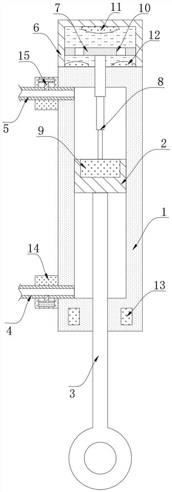
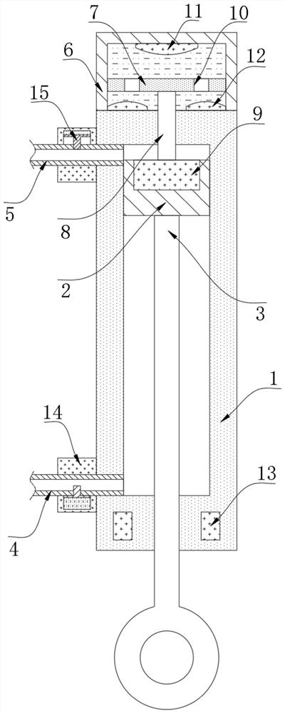
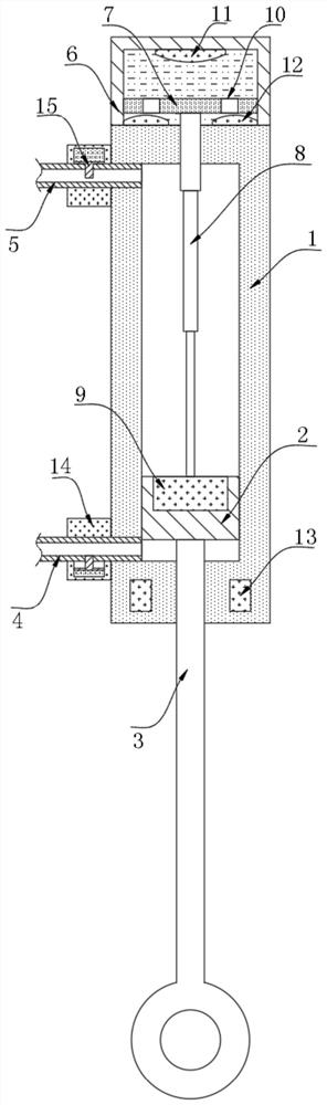
[0020] refer to Figure 1-3 , a buffer hydraulic oil cylinder, comprising a cylinder body 1, the inner wall of the cylinder body 1 is sealed and slidably connected with a piston 2, the side wall of the piston 2 is fixed with a pull rod 3 penetrating through the cylinder body 1, and the side wall of the cylinder body 1 is inserted with a retractable Pipe 4 and extension pipe 5, the outer wall of cylinder body 1 is fixed with buffer box 6, the inner wall of buffer box 6 is sealed and slidably connected with push plate 7, the side wall of push plate 7 is fixed with telescopic rod 8, and the side wall of piston 2 is fixed with Magnet 9, expansion rod 8 run through the side wall of cylinder body 1 and are fixed with magnet block 9, and the side wall of expansion rod 8 is sealed and slidably connected with cylinder body 1, and telescopic section is positioned at cylinder body 1 inside, and the inside of buffer box 6 is provided with There is a buffer mechanism, two current limiting ...


PUM


Abstract

The invention discloses a buffer hydraulic oil cylinder. The hydraulic oil cylinder comprises a cylinder body, a piston is connected to the inner wall of the cylinder body in a sealed and sliding manner, a pull rod penetrating through the cylinder body is fixed to the side wall of the piston, a contraction pipe and an extension pipe are inserted into the side wall of the cylinder body in a penetrating manner, and a buffer box is fixed to the outer wall of the cylinder body. A push plate is connected to the inner wall of the buffer box in a sealed and sliding manner, a telescopic rod is fixed to the side wall of the push plate, and a magnetic block is fixed to the side wall of the piston. The buffer hydraulic oil cylinder has the advantages that magnetorheological fluid is arranged in the buffer box, the magnetic block is arranged on the piston, and when the piston gets close to the buffer box at a high speed, magnetic force acts on the magnetorheological fluid, so that the fluidity ofthe magnetorheological fluid is reduced, the movement of the push plate is limited, the movement of the piston is limited, and furthermore, the piston does not violently collide with the inner wall ofthe cylinder body, a buffering effect is achieved on movement of the piston, and the service life of the cylinder body and the service life of the piston are prolonged.

Description

technical field [0001] The invention relates to the technical field of hydraulic cylinders, in particular to a buffer hydraulic oil cylinder. Background technique [0002] Hydraulic cylinders generally refer to hydraulic cylinders, which are hydraulic actuators that convert hydraulic energy into mechanical energy and perform linear reciprocating motion. It is simple in structure and reliable in operation. It is mainly used in machinery. It is the most important component of construction machinery and an important core component that provides power for machinery. [0003] The hydraulic cylinder relies on the injection and outflow of oil to realize the moving operation of the piston. The piston moves at a high speed under the promotion of hydraulic oil, so the collision with the end of the cylinder is inevitable. However, some of the existing hydraulic cylinders are not equipped with buffer equipment, and some The effect of buffering equipment is poor, resulting in the reduct...

Claims


Application Information

Patent Timeline
IPC IPC(8): F15B15/22F15B15/14
CPCF15B15/22F15B15/14
Inventor 崔蝶
Owner 常德市富斯特液压油缸有限公司
Why Eureka
Try Eureka