Surface roughness measuring instrument with adjustment limiting function

A technology with surface roughness and limited functions, which is applied in the field of surface roughness measuring instruments with adjustable and limited functions, can solve the problems of low measurement accuracy, narrow adaptation range, and large manpower operation, so as to achieve wide measurement range and improve measurement efficiency Effect

Pending Publication Date: 2021-02-05
宜兴高泰克精密机械有限公司
View PDF7 Cites 7 Cited by
  • Summary
  • Abstract
  • Description
  • Claims
  • Application Information

AI Technical Summary

Problems solved by technology

[0003] The surface roughness measurement of existing mechanical parts is generally to fix the surface roughness measuring instrument on the operating table, place the processed workpiece on the operating table, make the measuring surface of the workpiece close to the probe of the surface roughness measuring instrument, and realize the measurement of the workpiece. The measurement of the surface roughness of the surface, this method consumes a lot of manpower in the measurement, the measurement accuracy is low, and the measurement efficiency is very low, and the position of the surface roughness measuring instrument in the surface roughness measurement of the existing mechanical parts is fixed and cannot be changed. The direction of the probe of the surface roughness measuring instrument is difficult to measure accurately for some workpieces with a slope on the surface, and the scope of application is relatively narrow. Therefore, we propose a surface roughness measuring instrument with the function of adjusting and limiting

Method used


Image

  • Surface roughness measuring instrument with adjustment limiting function
  • Surface roughness measuring instrument with adjustment limiting function
  • Surface roughness measuring instrument with adjustment limiting function

Examples


Embodiment Construction

[0021] The following will clearly and completely describe the technical solutions in the embodiments of the present invention with reference to the accompanying drawings in the embodiments of the present invention. Obviously, the described embodiments are only some, not all, embodiments of the present invention. Based on the embodiments of the present invention, all other embodiments obtained by persons of ordinary skill in the art without making creative efforts belong to the protection scope of the present invention.

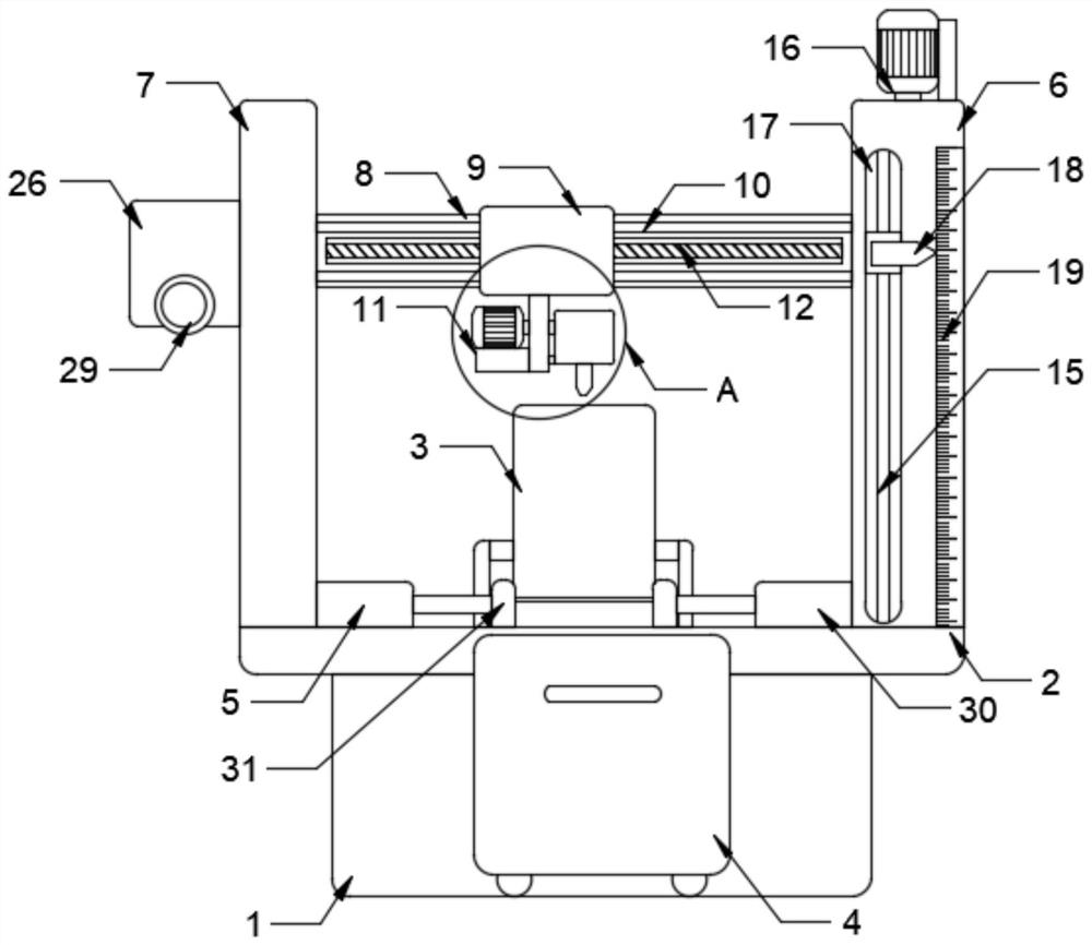
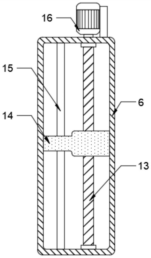
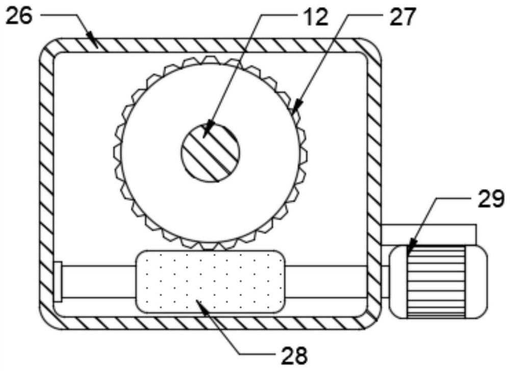
[0022] see figure 1 , the present invention provides a technical solution: a surface roughness measuring instrument with an adjustable and limited function, including a support base 1 and a support platform 2, the support platform 2 is installed on the top of the support base 1, and also includes: a feeding mechanism 3 , receiving car 4, clamping mechanism 5, support column 6, support plate 7, lifting rod 8, moving plate 9 and measuring mechanism 11, the top t...


PUM


Abstract

The invention discloses a surface roughness measuring instrument with an adjustment limiting function. The instrument comprises a supporting seat, a supporting table arranged at the top of the supporting seat, a feeding mechanism, a receiving trolley, a clamping mechanism, a supporting column, a supporting plate, a lifting rod, a moving plate and a measuring mechanism, the supporting column and the supporting plate are fixedly arranged at the two ends of the top of the supporting table respectively, the lifting rod is arranged between the supporting column and the supporting plate, the liftingrod is slidably connected between the supporting column and the supporting plate, the moving plate is slidably connected to the surface of the lifting rod, the measuring mechanism is arranged at thebottom of the moving plate, and sliding rods are symmetrically arranged on the surface of the lifting rod. According to the surface roughness measuring instrument, the height and the horizontal position of the surface roughness measuring instrument can be adjusted, the surface roughness measuring instrument can be rotated to a certain degree through the arrangement of a gear motor, a mounting plate and an arc-shaped groove, a workpiece with the surface at a certain gradient can be measured conveniently, and the measuring range is wide.

Description

technical field [0001] The invention relates to the technical field of surface roughness measuring instruments, in particular to a surface roughness measuring instrument with the function of regulating and limiting. Background technique [0002] Surface roughness is an important precision index of mechanical parts, which is generally formed by the processing method used and other factors, such as the friction between the tool and the surface of the part during processing, the plastic deformation of the surface layer metal when the chips are separated, and the process High-frequency vibration in the system, etc., to measure the surface roughness of the workpiece requires the use of a surface roughness measuring instrument. [0003] The surface roughness measurement of existing mechanical parts is generally to fix the surface roughness measuring instrument on the operating table, place the processed workpiece on the operating table, make the measuring surface of the workpiece ...

Claims


Application Information

Patent Timeline
Patent Type & Authority Applications(China)
IPC IPC(8): G01B21/30F16M11/04F16M11/18F16M11/10B65G59/06B65G47/82
CPCG01B21/30F16M11/045F16M11/046F16M11/18F16M11/105B65G59/067B65G47/82
Inventor 许栩曹光春
Owner 宜兴高泰克精密机械有限公司
Why Eureka
Try Eureka