Oil supplementing device for transformer

An oil replenishing device and transformer technology, applied in the field of transformers, can solve problems such as oil level drop, bubble generation, flashover, etc.

Inactive Publication Date: 2021-02-05
梁妙玲
View PDF0 Cites 0 Cited by
  • Summary
  • Abstract
  • Description
  • Claims
  • Application Information

AI Technical Summary

Problems solved by technology

[0002] When the fully sealed oil-immersed transformer is filled with oil, the height of the oil level in the oil injection pipe must be higher than the height of the high-voltage porcelain sleeve of the fully-sealed oil-immersed transformer, otherwise the transformer may occur due to lack of oil in the high-voltage porcelain sleeve during operation. Flashover; the current method of replenishing oil is to insert a conical funnel into the upper opening of the oil injection pipe, and use an oil pot to add oil slowly into the funnel. Since the inner diameter of the oil injection pipe is only 28-30mm, it is impossible to see clearly the inside of the oil injection pipe with the naked eye. If the oil level is high or low, it will often cause the target oil level not to be added or the oil level to be too much and overflow, making the tank cover full of oil
Secondly, there are still disadvantages: it is inevitable that there will be air bubbles when refueling under atmospheric pressure, and it will take a long time for the air bubbles to be discharged. A kind of oil supply device for transformer is proposed

Method used


Image

  • Oil supplementing device for transformer
  • Oil supplementing device for transformer
  • Oil supplementing device for transformer

Examples


Embodiment Construction

[0024] The following will clearly and completely describe the technical solutions in the embodiments of the present invention with reference to the accompanying drawings in the embodiments of the present invention. Obviously, the described embodiments are only some, not all, embodiments of the present invention. Based on the embodiments of the present invention, all other embodiments obtained by persons of ordinary skill in the art without making creative efforts belong to the protection scope of the present invention.

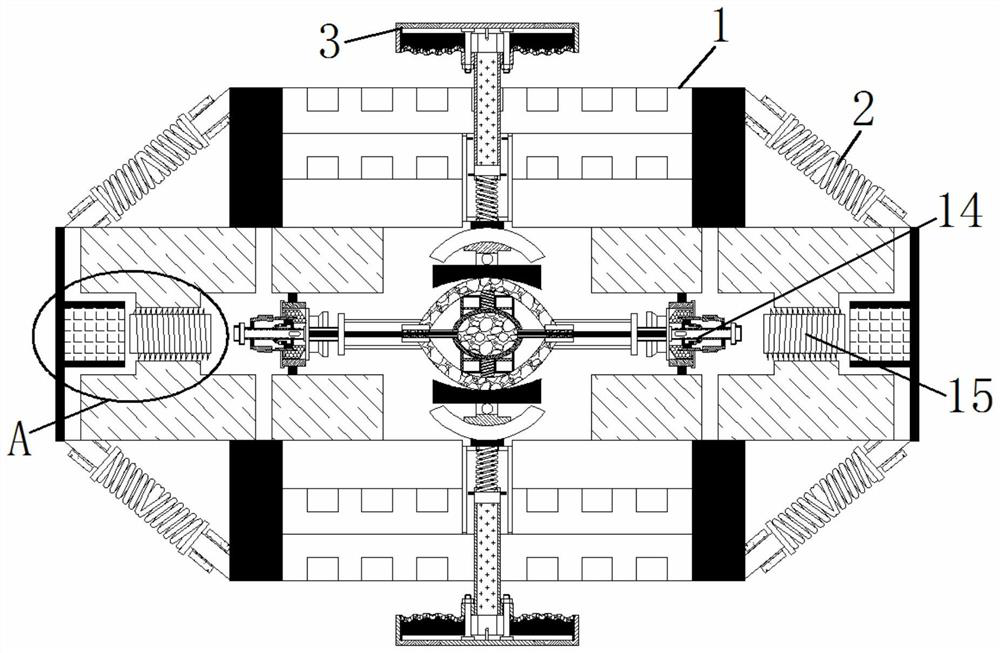
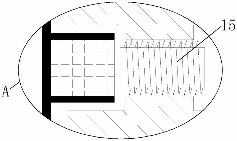
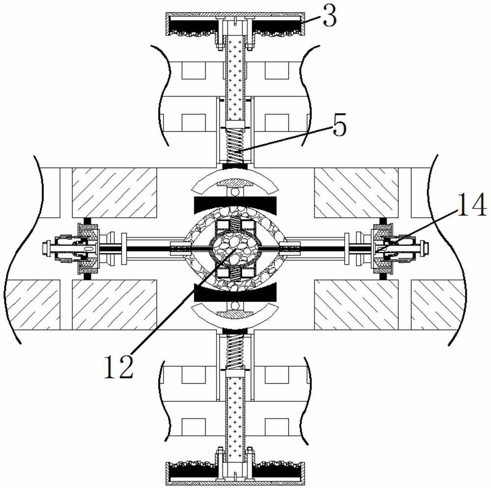
[0025] see Figure 1-7 , an oil supply device for a transformer, comprising a transformer main body 1, a receiving spring 2 is fixedly connected to the outer side of the transformer main body 1, a pressing plate 3 is fixedly installed on the outer side of the transformer main body 1, and a pressing rod is fixedly connected to the inner side of the pressing plate 3 4. The end of the pressing rod 4 away from the pressing plate 3 is fixedly connected with the pre...


PUM


Abstract

The invention relates to the technical field of transformers, and discloses an oil supplementing device for a transformer, which comprises a transformer main body, the outer side of the transformer main body is fixedly connected with a bearing spring, the outer side of the transformer main body is fixedly provided with a pressing plate, and the inner side of the pressing plate is fixedly connectedwith a pressing rod; one end, away from the pressing plate, of the pressing rod is fixedly connected with a pressing spring; one end, away from the pressing rod, of the pressing spring is fixedly connected with an arc-shaped plate; one end, away from the pressing spring, of the arc-shaped plate is fixedly connected with a bearing block, and one end, away from the arc-shaped plate, of the bearingblock is fixedly connected with an abutting block. According to the oil supplementing device for the transformer, lubricating oil is contained in the oil bag, the oil bag is pressed to deform based onexternal pressure, the lubricating oil contained in the oil bag is sprayed out of the oil outlet spray head through the oil outlet pipe and evenly sprayed to the variable pressure valve, and therefore the purpose of automatic oil supplementing of the interior of the transformer body is achieved.

Description

technical field [0001] The invention relates to the technical field of transformers, in particular to an oil replenishing device for transformers. Background technique [0002] When the fully sealed oil-immersed transformer is filled with oil, the height of the oil level in the oil injection pipe must be higher than the height of the high-voltage porcelain sleeve of the fully-sealed oil-immersed transformer, otherwise the transformer may occur due to lack of oil in the high-voltage porcelain sleeve during operation. Flashover; the current method of replenishing oil is to insert a conical funnel into the upper opening of the oil injection pipe, and use an oil pot to add oil slowly into the funnel. Since the inner diameter of the oil injection pipe is only 28-30mm, it is impossible to see clearly the inside of the oil injection pipe with the naked eye. If the oil level is high or low, the target oil level is often not added or the oil level is too much to overflow, and the tan...

Claims


Application Information

Patent Timeline
Patent Type & Authority Applications(China)
IPC IPC(8): H01F27/14
CPCH01F27/14
Inventor 梁妙玲
Owner 梁妙玲
Why Eureka
Try Eureka