
Equipment monitoring method, device and system and computer readable storage medium

A device monitoring and device technology, applied in the field of the Internet of Things, can solve problems such as insufficient intelligence, inability to control the operation of home appliances, and multiple computing resources

Pending Publication Date: 2021-02-05
SHENZHEN TCL NEW-TECH CO LTD
View PDF24 Cites 0 Cited by
  • Summary
  • Abstract
  • Description
  • Claims
  • Application Information

AI Technical Summary

Problems solved by technology

[0002] With the improvement of the quality of life and the continuous change of the living environment, the application of home appliances is becoming more and more common, and there are more and more home appliances on the market. However, the function control of most home appliances is mainly based on manual and infrared. Remote control requires the user to give instructions at a short distance to realize the control of the home appliance. Once the control distance is exceeded, the user will not be able to control the operation of the home appliance
[0003] For this reason, the existing technology proposes a remote monitoring method based on mobile phone terminals. The principle is that through the World Wide Web, the user issues instructions on the mobile terminal to control the remote home appliances and monitor the operating status of the home appliances in real time. However, this In the process of remote monitoring of home appliances, it needs to consume more computing resources of mobile terminals, and the control method is relatively rigid, requiring the user to input specified operating parameters to achieve precise control. It can be seen that the existing remote control methods are not smart enough to Intelligent and flexible monitoring of home appliances

Method used


Image

  • Equipment monitoring method, device and system and computer readable storage medium
  • Equipment monitoring method, device and system and computer readable storage medium

Examples


Embodiment Construction

[0063]It should be understood that the specific embodiments described here are only used to explain the present invention, not to limit the present invention.

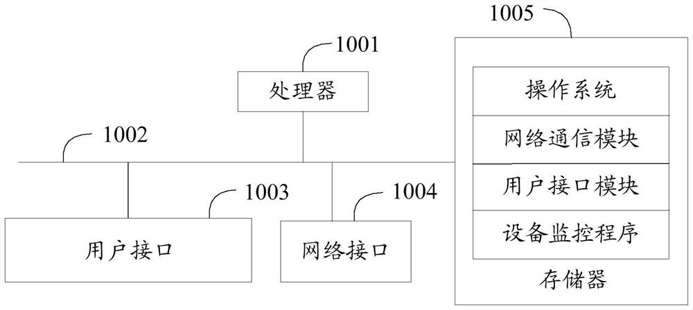
[0064] Such as figure 1 as shown, figure 1 It is a schematic diagram of the system structure of the hardware operating environment involved in the solution of the embodiment of the present invention.

[0065] The system in this embodiment of the present invention includes a terminal or server device.

[0066] Such as figure 1 As shown, the system may include: a processor 1001 , such as a CPU, a network interface 1004 , a user interface 1003 , a memory 1005 , and a communication bus 1002 . Wherein, the communication bus 1002 is used to realize connection and communication between these components. The user interface 1003 may include a display screen (Display), an input unit such as a keyboard (Keyboard), and the optional user interface 1003 may also include a standard wired interface and a wireless interface. Optio...


PUM


Abstract

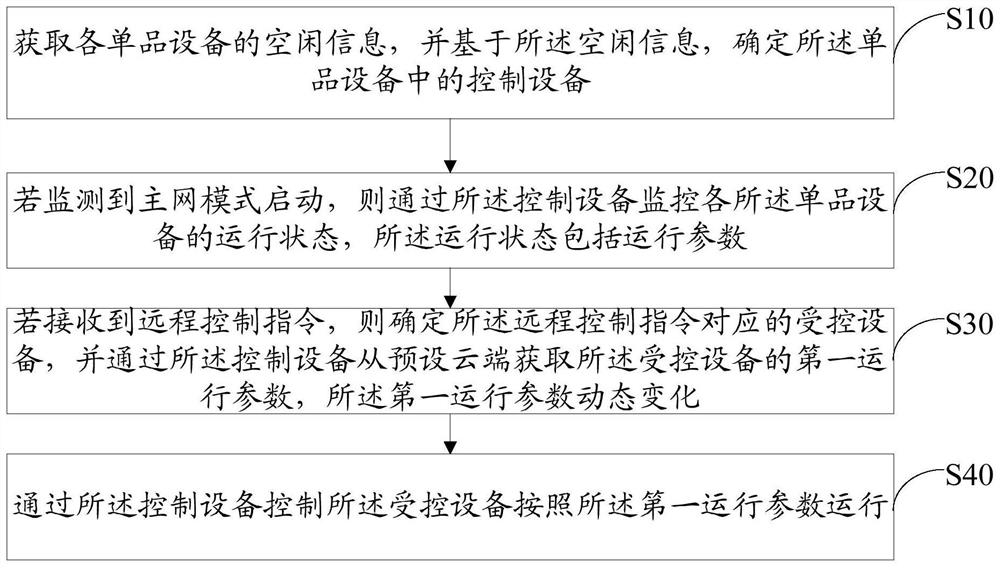
The invention discloses an equipment monitoring method which comprises the following steps: acquiring idle information of single equipment, and determining control equipment in the single equipment based on the idle information; if it is monitored that a main network mode is started, monitoring the operation states of the single equipment through the control equipment, wherein the operation statescomprise operation parameters; if a remote control instruction is received, determining controlled equipment corresponding to the remote control instruction, and obtaining a first operation parameterof the controlled equipment from a preset cloud through the control equipment; and controlling the controlled equipment to operate according to the first operation parameter through the control equipment. The invention further discloses an equipment monitoring device and system and a computer readable storage medium. According to the method, the computing pressure of the original mobile phone terminal is shared by the idle single equipment, and the optimal operating parameters are obtained at the preset cloud, so that the remote intelligent monitoring of the single equipment is realized.

Description

technical field [0001] The present invention relates to the technical field of the Internet of Things, in particular to an equipment monitoring method, device, system and computer-readable storage medium. Background technique [0002] With the improvement of the quality of life and the continuous change of the living environment, the application of home appliances is becoming more and more common, and there are more and more home appliances on the market. However, the function control of most home appliances is mainly based on manual and infrared. Remote control requires the user to give instructions at close range to control the home appliance. Once the control distance is exceeded, the user will not be able to control the operation of the home appliance. [0003] For this reason, the existing technology proposes a remote monitoring method based on a mobile phone terminal. The principle is that the user issues instructions on the mobile phone terminal through the World Wide...

Claims


Application Information

Patent Timeline
IPC IPC(8): H04L12/28H04L29/06H04L29/08G16Y10/80G16Y20/10G16Y20/20G16Y40/30
CPCH04L12/2816H04L12/2823H04L67/025H04L67/12H04L63/083H04L63/0876G16Y10/80G16Y20/10G16Y20/20G16Y40/30Y02P90/02
Inventor 李海锋
Owner SHENZHEN TCL NEW-TECH CO LTD
Learn More