Multifunctional neurological examination bed

A technology of neurology and examination bed, which is applied in the field of medical equipment, can solve problems such as inaccurate examination results, inconvenient patients, poor practicability and applicability, etc., and achieve the effect of improving practicability and applicability, and improving practicability

Inactive Publication Date: 2021-02-09
杭州华慧医药科技有限公司
View PDF0 Cites 0 Cited by
  • Summary
  • Abstract
  • Description
  • Claims
  • Application Information

AI Technical Summary

Problems solved by technology

[0005] The purpose of the present invention is: in order to solve the problem that the existing neurology examination bed is inconvenient to fix the patient, so that the patient is easy to move during the examination process, resulting in inaccurate examination results, and at the same time, the device is not convenient for adjusting the height of the bed board. It makes it inconvenient for some patients to lie on the examination bed or stand up from the examination bed, and it is inconvenient to adjust the examination position of the examination mechanism on the examination bed, which makes the practicability and applicability of the device poor. The present invention provides a Multifunctional Neurology Examination Table

Method used


Image

  • Multifunctional neurological examination bed
  • Multifunctional neurological examination bed
  • Multifunctional neurological examination bed

Examples


Embodiment 1

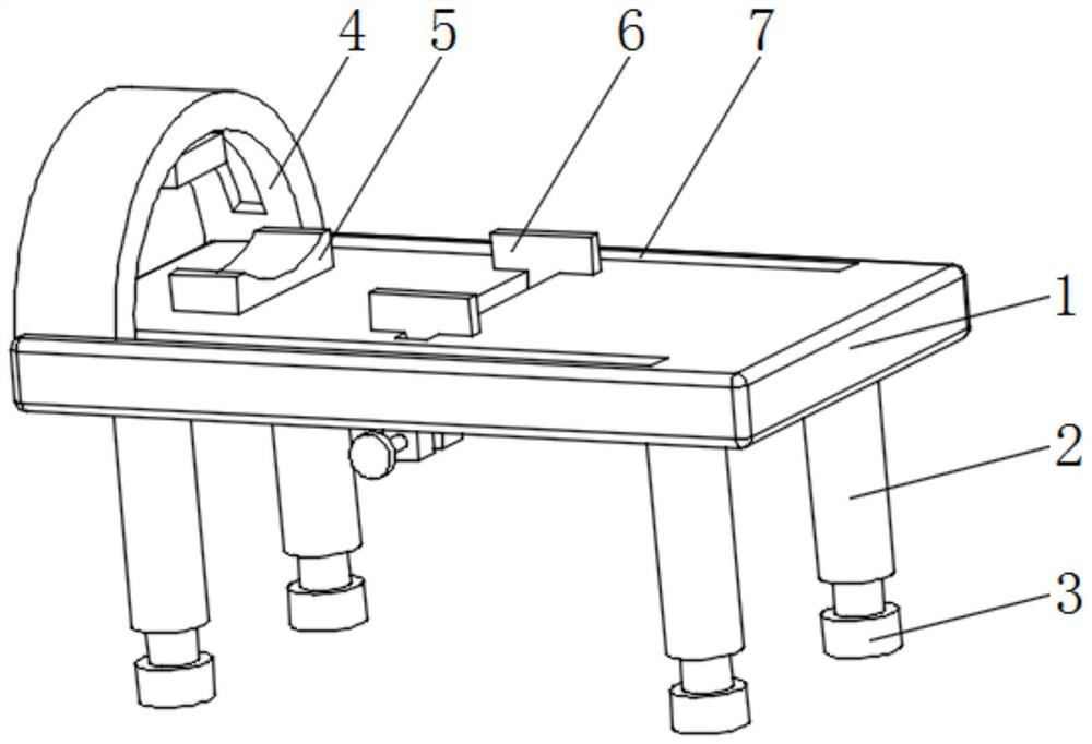
[0028] see Figure 1-4 , a multifunctional neurology examination bed, comprising a bed board 1, a fixed chute 15 is provided in the middle of the top of the bed board 1, and fixed slides 16 are symmetrically slidably connected to both ends of the fixed chute 15, and there are two fixed slides 16, two The tops of the two fixed slide plates 16 all stretch out the fixed chute 15 and are fixedly connected with the fixed splint 6, and both sides of the bottom middle part of the bed board 1 are fixedly connected with the fixed block 17, and the fixed block 17 is corresponding to the fixed slide plate 16. The middle part of the outer wall on one side corresponding to the block 17 is rotatably connected with a fixed screw 19, one end of the fixed screw 19 runs through the fixed block 17 and is fixedly connected with a fixed hand wheel 20, and the front and rear sides of the top of the bed board 1 are provided with T-shaped chute symmetrically. 7. The inside of the T-shaped chute 7 is ...

Embodiment 2

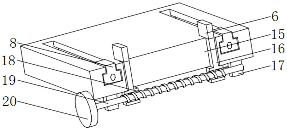
[0031] see figure 1 and Figure 4 , the present embodiment is further optimized on the basis of embodiment 1, specifically, the bottom ends of the two fixed slide plates 16 extend out of the fixed chute 15 and are respectively provided with fixed threaded holes 18 with opposite rotation directions. Each fixed slide plate 16 is threadedly connected with the outer wall of the fixed screw rod 19 through the fixed threaded hole 18.

[0032] Specifically, there are four fixed support columns 2 and four support bases 3, and the four fixed support columns 2 and the support bases 3 are evenly distributed in a rectangular shape, and the four support bases 3 correspond to the four fixed support columns 2 respectively. .

[0033] Specifically, the middle part of the bottom end of the fixed support column 2 is provided with a lifting chute 22, and the inside of the lifting chute 22 is slidably connected with a lifting support column 23. The middle part of the top of 3 is fixedly connec...

Embodiment 3

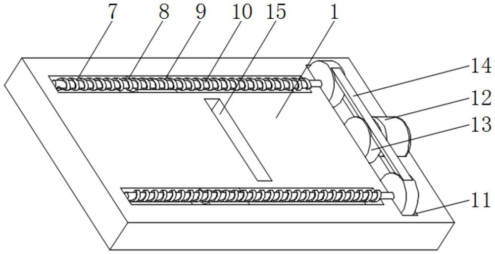
[0037] see figure 2 and image 3 , the present embodiment is optimized as follows on the basis of Example 1 or Example 2, specifically, the internal rotation of the T-shaped chute 7 is connected with an adjusting screw 10, and one side of the outer wall of the T-shaped slider 8 is provided with an adjusting threaded hole 9. The T-shaped slider 8 is threadedly connected with the outer wall of the adjusting screw 10 through the adjusting threaded hole 9 .

[0038] Specifically, one end of the inner wall of the T-shaped chute 7 is provided with a transmission belt groove 11, and one end of the two adjusting screws 10 is respectively corresponding to the two ends of the inner wall of the transmission belt groove 11 and extends into the transmission belt groove 11 to be rotationally connected.

[0039] Specifically, the middle part of one side of the inner wall of the transmission belt groove 11 is fixedly connected with an adjustment motor 12, and the output shaft of the adjustm...


PUM


Abstract

The invention discloses a multifunctional neurological examination bed, and relates to the technical field of medical instruments. The examination bed comprises a bed plate, wherein a fixing sliding groove is formed in middle of a top end of the bed plate, fixing sliding plates are symmetrically and slidably connected to two ends of an interior of the fixing sliding groove, tops of the fixing sliding plates extend out of the fixing sliding groove and are fixedly connected with fixing clamping plates, fixing blocks are fixedly connected to two sides of middle of a bottom end of the bed plate, fixing screw rods are rotatably connected to middles of outer walls of corresponding sides of the two fixing blocks, one ends of the fixing screw rods penetrate through the fixing blocks and are fixedly connected with fixing hand wheels, T-shaped sliding grooves are symmetrically formed in a front side and a rear side of a top of the bed plate, a T-shaped sliding block is slidably connected into the T-shaped sliding groove, and middle of a top end of the T-shaped sliding block extends out of the T-shaped sliding groove and is fixedly connected with an examination mechanism. According to the examination bed, by arranging the fixing clamping plates, the fixing sliding plates, the fixing blocks, the fixing screw rods and the fixing hand wheels, a patient needing to be examined can be fixed.

Description

technical field [0001] The invention relates to the technical field of medical devices, and more specifically relates to a multifunctional neurology examination bed. Background technique [0002] Examination of the neurology department in medical treatment often requires an examination bed. The existing examination bed of the neurology department is not convenient for fixing the patient, so that the patient is easy to move during the examination process, resulting in inaccurate examination results. At the same time, the device is not It is convenient to adjust the height of the bed board, which makes it inconvenient for some patients to lie on the examination bed or stand up from the examination bed, and it is not convenient to adjust the inspection position of the inspection mechanism on the examination bed, which makes the practicability and applicability of the device poor . [0003] Therefore, it is necessary to propose a multifunctional neurology examination bed to sol...

Claims


Application Information

Patent Timeline
Patent Type & Authority Applications(China)
IPC IPC(8): A61G13/00A61G13/06A61G13/10
CPCA61G13/0018A61G13/06A61G13/10
Inventor 陈贝灵
Owner 杭州华慧医药科技有限公司
Why Eureka
Try Eureka