
Motor wire end welding, positioning and clamping tool

A welding positioning and clamping tooling technology, which is applied in the direction of electromechanical devices, welding equipment, auxiliary welding equipment, etc., can solve the problems of low efficiency and difficulty in ensuring welding quality, so as to improve the degree of automation, ensure the welding quality of wire ends, and effectively The effect of compression positioning

Pending Publication Date: 2021-02-09
JULI AUTOMATION EQUIP ZHEJIANG CO LTD
View PDF5 Cites 1 Cited by
  • Summary
  • Abstract
  • Description
  • Claims
  • Application Information

AI Technical Summary

Problems solved by technology

This manual operation is obviously not efficient, and the welding quality is difficult to guarantee

Method used


Image

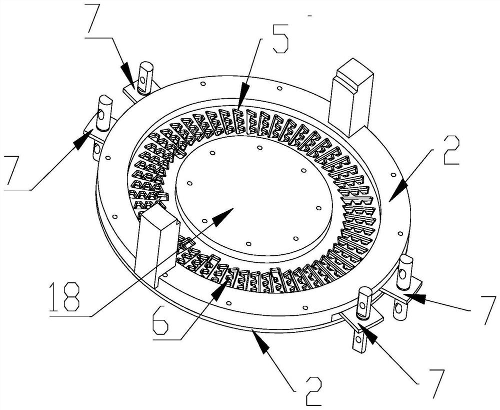
  • Motor wire end welding, positioning and clamping tool
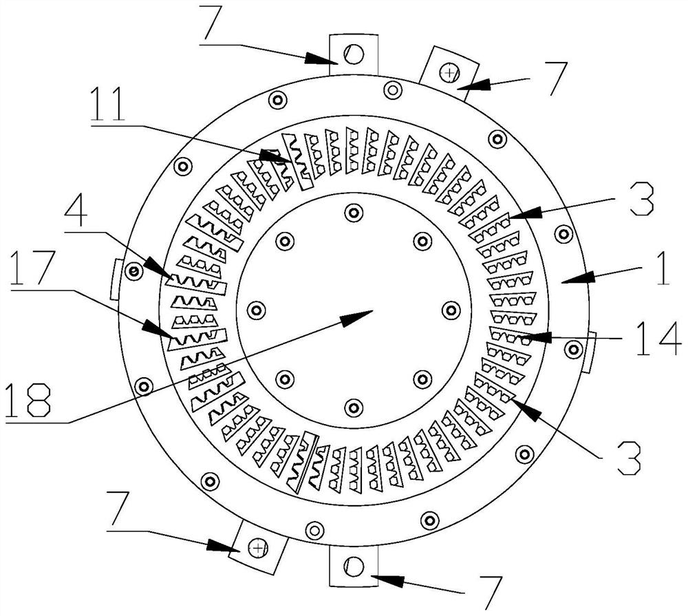
  • Motor wire end welding, positioning and clamping tool
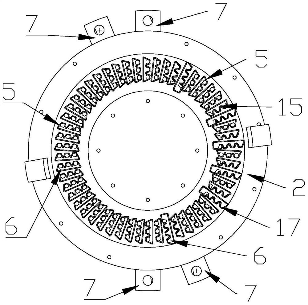
  • Motor wire end welding, positioning and clamping tool

Examples


Embodiment Construction

[0017] The technical solutions of the present invention will be clearly and completely described below in conjunction with the accompanying drawings. Apparently, the described embodiments are some of the embodiments of the present invention, but not all of them. Based on the embodiments of the present invention, all other embodiments obtained by persons of ordinary skill in the art without making creative efforts belong to the protection scope of the present invention.

[0018] In the description of the present invention, it should be noted that the terms "center", "upper", "lower", "left", "right", "vertical", "horizontal", "inner", "outer" etc. The indicated orientation or positional relationship is based on the orientation or positional relationship shown in the drawings, and is only for the convenience of describing the present invention and simplifying the description, rather than indicating or implying that the referred device or element must have a specific orientation, ...


PUM


Abstract

The invention discloses a motor wire end welding, positioning and clamping tool. The tool comprises an upper rotary disc and a lower rotary disc; a cylinder is fixedly installed in the middle of the lower rotary disc, a rotary hole is formed in the middle of the upper rotary disc, the cylinder is notably inserted into the rotary hole, a plurality of upper clamping hole sets are formed in the upperrotary disc, and each upper clamping hole set comprises a plurality of upper clamping holes which are linearly arranged; and a plurality of lower clamping hole sets are formed in the lower rotary disc, each lower clamping hole set comprises a plurality of lower clamping holes which are linearly arranged, the upper clamping holes correspond to the lower clamping holes in a one-to-one mode, and rotary arms are fixedly connected to the two sides of the upper rotary disc and the two sides of the lower rotary disc respectively. According to the motor wire end welding, positioning and clamping tool, wire ends in a motor winding can be rapidly and effectively pressed and positioned, wire end welding is facilitated, the wire end welding quality is guaranteed, the automation degree of the motor production process is improved, and the motor production efficiency is improved.

Description

technical field [0001] The invention belongs to the technical field of motor production equipment, and in particular relates to a welding, positioning and clamping tool for wire ends of a motor. Background technique [0002] The motor includes many parts such as stator, rotor and winding. In order to meet various performance requirements, new high-end motors such as motors for new energy vehicles have more complex structures and more diverse processes involved in the production process. The winding of the motor for new energy vehicles is formed by welding the copper wires after the copper wires are plugged in. Due to the large number of wire ends that need to be welded, the copper wire has deformation and elastic effects, and there are gaps and dislocations between the wire ends that need to be welded to each other. Workers need to clamp the two wire ends before welding. The efficiency of manual operation is obviously not high like this, and the welding quality is difficul...

Claims


Application Information

Patent Timeline
IPC IPC(8): B23K37/04H02K15/00B23K101/32B23K101/36
CPCB23K37/0443H02K15/0068B23K2101/36B23K2101/32
Inventor 张晓军吴应龙章日平张伟中张勇
Owner JULI AUTOMATION EQUIP ZHEJIANG CO LTD
Features
  • Generate Ideas
  • Intellectual Property
  • Life Sciences
  • Materials
  • Tech Scout
  • Unparalleled Data Quality
  • Higher Quality Content
  • 60% Fewer Hallucinations
Learn More