Engineering surveying and mapping device based on unmanned aerial vehicle

The technology of a surveying and mapping device and unmanned aerial vehicle, which is applied in the directions of unmanned aerial vehicles, rotorcraft, motor vehicles, etc., can solve the problems of easy tilting of unmanned aerial vehicles, affecting the process of engineering surveying and mapping, damage of unmanned aerial vehicles or surveying and mapping cameras, etc. Achieve the effect of stabilizing the drone body and avoiding damage

Inactive Publication Date: 2021-02-09
刘占利
View PDF0 Cites 4 Cited by
  • Summary
  • Abstract
  • Description
  • Claims
  • Application Information

AI Technical Summary

Problems solved by technology

[0003] Existing engineering surveying and mapping usually requires the use of UAVs. Due to the complex outdoor environment and terrain, UAVs are easy to tilt when landing. Cause damage to drones or surveying and mapping cameras, affecting the engineering surveying and mapping process

Method used


Image

  • Engineering surveying and mapping device based on unmanned aerial vehicle
  • Engineering surveying and mapping device based on unmanned aerial vehicle
  • Engineering surveying and mapping device based on unmanned aerial vehicle

Examples


Embodiment 1

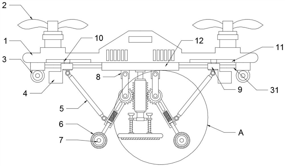
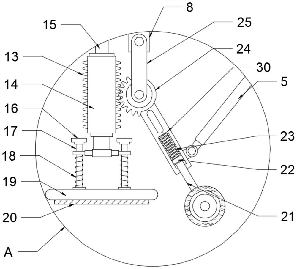
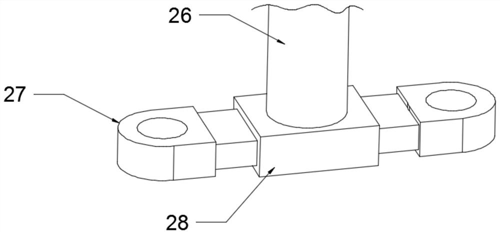
[0022] see Figure 1-3 , a UAV-based engineering surveying and mapping device, including a UAV body 1, a spiral blade 2, and a surveying and mapping camera 3, the surveying and mapping camera 3 is symmetrically and fixedly installed on the lower surface of the UAV body 1, and the UAV The support plate 12 is fixedly installed on the lower surface of the body 1, and the support rod 15 is fixedly installed on the lower surface of the support plate 12. The end of the support rod 15 away from the support plate 12 is installed in the support sleeve 14, and the support rod 15 and the support sleeve The cylinder 14 is slidingly connected, and the bottom end of the support sleeve 14 is fixedly installed with a pillar 26, and the end of the pillar 26 away from the support sleeve 14 is fixedly connected to the support 28, and the left and right ends of the support 28 are symmetrically provided with sliding seats 27, so The sliding seat 27 is installed on the outside of the shock absorbin...

Embodiment 2

[0028] see Figure 1-4 , on the basis of Embodiment 1, in order to protect the surveying and mapping camera 3 when landing, guide rods 31 are arranged symmetrically at the left and right ends of the support plate 12, and the end of the guide rod 31 away from the support plate 12 is above the surveying and mapping camera 3. The base is fixedly connected, the surface of the guide rod 31 is provided with a movable seat 9, and the movable seat 9 is slidingly connected with the guide rod 31, and the push rod 5 is movably connected above the buffer sleeve 30 on the left and right sides, and the push rod 5 is away from One end of the buffer sleeve 30 is movably connected with the movable seat 9, and the protective cover 4 is fixedly connected to the bottom of the movable seat 9 on the left and right sides. 5 Push the movable seat 9 to move toward the surveying and mapping camera 3 on the surface of the guide rod 31, and the movable seat 9 drives the lower protective cover 4 to move t...


PUM


Abstract

The invention discloses an engineering surveying and mapping device based on an unmanned aerial vehicle, and relates to the technical field of engineering surveying and mapping auxiliary equipment, the engineering surveying and mapping device comprises an unmanned aerial vehicle body, spiral blades and surveying and mapping cameras, the surveying and mapping cameras are symmetrically and fixedly installed on the lower surface of the unmanned aerial vehicle body; the lower surface of the unmanned aerial vehicle body is fixedly provided with a supporting plate, and a supporting rod is fixedly mounted on the lower surface of the supporting plate; the end, away from the supporting plate, of the supporting rod is installed in a supporting sleeve, and the supporting column is fixedly installed at the bottom end of the supporting sleeve. when the unmanned aerial vehicle body lands, the supporting idler wheels on the left side and the right side make contact with the ground firstly, the buffersprings convert external acting force into elastic force to achieve preliminary damping, and the idler wheels on the left side and the right side move outwards at the same time, the half gears on theleft side and the right side are meshed with the rack plates to drive the supporting sleeve and the damping supporting plates below to move downwards, the damping supporting plate make contact with the ground, the effect of stabilizing the unmanned aerial vehicle body is achieved, and the damping springs convert external acting force into elastic force.

Description

technical field [0001] The invention relates to the technical field of engineering surveying and mapping auxiliary equipment, in particular to a drone-based engineering surveying and mapping device. Background technique [0002] Surveying and mapping devices, simply speaking, are instruments and devices for data acquisition, processing, and output designed and manufactured for surveying and mapping operations, and various orientation, ranging, Instruments for angle measurement, height measurement, mapping and photogrammetry. [0003] Existing engineering surveying and mapping usually requires the use of UAVs. Due to the complex outdoor environment and terrain, UAVs are easy to tilt when landing. It will cause damage to the drone or the surveying and mapping camera, which will affect the engineering surveying and mapping process. Contents of the invention [0004] The object of the present invention is to provide an engineering surveying and mapping device based on a UAV,...

Claims


Application Information

Patent Timeline
Patent Type & Authority Applications(China)
IPC IPC(8): B64C25/62B64D47/08B64C27/08
CPCB64C25/62B64D47/08B64C27/08B64U10/10B64U2101/30
Inventor 刘占利
Owner 刘占利
Why Eureka
Try Eureka