Anti-wind device for port logistics

A windproof device and logistics technology, applied in the direction of safety devices, transportation and packaging, load suspension components, etc., can solve problems such as cable breakage, and achieve the effects of avoiding dumping and separation, good wind resistance, and long service life

Pending Publication Date: 2021-02-09
徐晓宁
0 Cites 0 Cited by

AI-Extracted Technical Summary

Problems solved by technology

[0004] The purpose of the present invention is to provide a windproof device for port logistics to solve the problem that the chain structure proposed in the above backgro...

Method used

Further, the outer wall of the first embedded rod 11 and the second inserted rod 14 are all fixedly provided with projections, both sides of the notch inside the pre-embedded workpiece 2 are all provided with chute, and the projection is inserted in the chute. Inside, the stability of the movement of the first insert rod 11 and the second insert rod 14 can be improved, and the separation of the first insert rod 11 and the second insert rod 14 can be avoided, thereby improving the stability of the pre-embedded workpiece 2 .
Further, the outer wall of the second threaded rod 13 is sleeved with a cross bar, and the cross bar position is embedded inside the notch inside the workpiece 2 internal transverse, the second threaded rod 13 can be supported, avoiding the second threaded rod 13 The situation of shaking and disengagement occurs when the rotation occurs, so that the moving effect of the second insert rod 14 is better, and it is convenient to use.
Further, the top of embedded workpiece 2 is fi...

Abstract

The invention relates to the technical field of port logistics anti-wind, in particular to an anti-wind device for port logistics. The device comprises a mounting foundation, wherein a notch is formedin the mounting foundation, an embedded workpiece is fixedly mounted in the notch, a mounting block is fixedly mounted in the middle of the top end of the embedded workpiece, a first connecting locksleeve is arranged at the top end of the mounting block, and the outer wall of the first connecting lock sleeve is sleeved with a second connecting lock sleeve. According to the device, by arranging asupporting rod and a pressure spring, when the first connecting lock sleeve and the second connecting lock sleeve are stretched, the pressure spring can buffer a space between the first connecting lock sleeve and the second connecting lock sleeve, and then relieves pressure between the first connecting lock sleeve and the second connecting lock sleeve, so that the situation that the first connecting lock sleeve and the second connecting lock sleeve are broken after being used for a long time is avoided, the service life of the first connecting lock sleeve and the service life of the second connecting lock sleeve are longer, and an anti-wind effect of a crane is better.

Application Domain

Vibration suppression adjustmentsSafety gear

Technology Topic

Structural engineeringMechanical engineering +3

Image

  • Anti-wind device for port logistics
  • Anti-wind device for port logistics
  • Anti-wind device for port logistics

Examples

  • Experimental program(1)

Example Embodiment

[0019]The technical solutions in the embodiments of the present invention will be clearly and completely described below in conjunction with the accompanying drawings in the embodiments of the present invention. Obviously, the described embodiments are only a part of the embodiments of the present invention, rather than all the embodiments. Based on the embodiments of the present invention, all other embodiments obtained by those of ordinary skill in the art without creative work shall fall within the protection scope of the present invention.
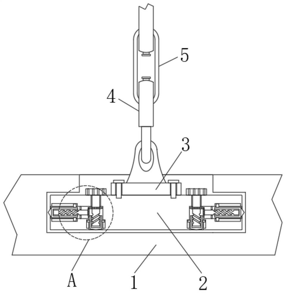
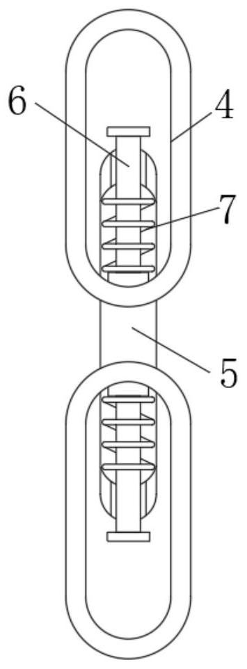
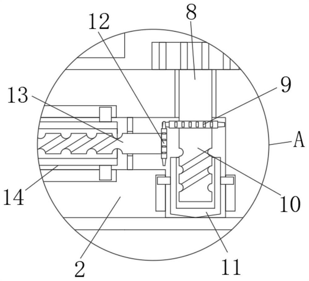
[0020]SeeFigure 1-4, An embodiment provided by the present invention:
[0021]A wind-proof device for port logistics, including an installation foundation 1, a notch is opened inside the installation foundation 1, and a pre-embedded workpiece 2 is fixedly installed inside the notch, and an installation is fixedly installed at the top middle position of the pre-buried workpiece 2 Block 3, the top of the mounting block 3 is provided with a first connecting lock sleeve 4, the outer wall of the first connecting lock sleeve 4 is sleeved with a second connecting lock sleeve 5, and the inside of the first connecting lock sleeve 4 is fixedly installed with a support rod 6, Both ends of the second connecting lock sleeve 5 are provided with holes. The second connecting lock sleeve 5 is sleeved on the outer wall of the support rod 6, and the outer wall of the support rod 6 is sleeved with a pressure spring 7, and the pressure spring 7 is located in the second connecting lock. Set of 5 inner walls.
[0022]Further, a rotating rod 8 is fixedly installed at the top end of the embedded workpiece 2, a vertical slot is provided on the inner wall of the embedded workpiece 2, and the rotating rod 8 extends to the inside of the slot, and the bottom end of the rotating rod 8 is fixedly installed with The first threaded rod 10, the outer wall of the first threaded rod 10 is sleeved with the first insert rod 11, and the rotating rod 8 is rotated, so that the rotating rod 8 drives the first threaded rod 10 to rotate, and then the first threaded rod 10 passes through the threaded structure By driving the first insert rod 11 to move, the first insert rod 11 can be embedded into the installation foundation 1, thereby increasing the stability between the installation foundation 1 and the embedded workpiece 2, and is convenient to use.
[0023]Further, the outer wall of the rotating rod 8 is fixedly installed with a first gear 9; the inner wall of the embedded workpiece 2 is provided with a transverse notch; the inside of the notch is fixedly installed with a second threaded rod 13, and the second threaded rod 13 is close to the first A second gear 12 is fixedly installed at the position of the gear 9. The second gear 12 meshes with the first gear 9. The outer wall of the second gear 12 is sleeved with a second insert rod 14. The rotation rod 8 drives the first The gear 9 rotates, then the first gear 9 drives the second gear 12 to rotate, and then the second gear 12 drives the second threaded rod 13 to rotate, so that the second threaded rod 13 can drive the second insert rod 14 to move through the threaded structure , The second insert rod 14 can be embedded into the installation foundation 1, and the first insert rod 11 can be used to make the pre-embedded workpiece 2 more stable, thereby making the first connecting lock sleeve 4 and the second connecting lock sleeve 5 more stable Better performance and easy to use.
[0024]Further, the top end of the rotating rod 8 is provided with a circular block, and the outer wall of the circular block is provided with a thread groove, and the circular block is located on the upper surface of the embedded workpiece 2, which can make the rotation of the rotating rod 8 more convenient.
[0025]Further, the outer walls of the first insert rod 11 and the second insert rod 14 are fixedly installed with bumps, and both sides of the slot inside the pre-embedded workpiece 2 are provided with sliding grooves, and the protrusions are inserted into the inside of the sliding groove. The stability of the movement of the first insert 11 and the second insert 14 is better, and the separation of the first insert 11 and the second insert 14 is avoided, thereby making the embedded workpiece 2 more stable.
[0026]Further, the outer wall of the second threaded rod 13 is sleeved with a cross rod, and the position of the cross rod is embedded in the transverse notch inside the workpiece 2, which can support the second threaded rod 13 to prevent the second threaded rod 13 from shaking when rotating. In addition, the moving effect of the second insert rod 14 is better and the use is convenient.
[0027]Working principle: When in use, put the embedded workpiece 2 into the installation foundation 1 for installation, rotate the rotating rod 8, and then make the rotating rod 8 drive the first threaded rod 10 to rotate, and then the first threaded rod 10 passes through the threaded structure Drive the first cog rod 11 to move, so that the first cog rod 11 can be embedded into the installation foundation 1. The rotation rod 8 drives the first gear 9 to rotate, and then the first gear 9 drives the second gear 12 to perform After turning, the second gear 12 drives the second threaded rod 13 to rotate, so that the second threaded rod 13 can drive the second insert rod 14 to move through the thread structure, and the second insert rod 14 can be embedded into the installation foundation 1. Cooperating with the first insert rod 11 makes the pre-embedded workpiece 2 more stable, which in turn makes the first connecting lock sleeve 4 and the second connecting lock sleeve 5 more stable.
[0028]Then when the external wind is strong, the crane pulls the first connecting lock sleeve 4 and the second connecting lock sleeve 5, and then the second connecting lock sleeve 5 squeezes the pressure spring 7, so that the pressure spring 7 can connect to the first connection. Buffer between the lock sleeve 4 and the second connecting lock sleeve 5, thereby reducing the pressure between the first connecting lock sleeve 4 and the second connecting lock sleeve 5, thereby increasing the first connecting lock sleeve 4 and the second connecting lock sleeve 5 life span, avoid the first connection lock sleeve 4 and the second connection lock sleeve 5 from breaking, so that the first connection lock sleeve 4 and the second connection lock sleeve 5 have better tensile force, better wind resistance, and convenient use , The above is the working principle of the whole program.
[0029]For those skilled in the art, it is obvious that the present invention is not limited to the details of the foregoing exemplary embodiments, and the present invention can be implemented in other specific forms without departing from the spirit or basic characteristics of the present invention. Therefore, from any point of view, the embodiments should be regarded as exemplary and non-limiting. The scope of the present invention is defined by the appended claims rather than the foregoing description, and therefore it is intended to fall within the claims. All changes within the meaning and scope of equivalent elements of are included in the present invention. Any reference signs in the claims should not be regarded as limiting the claims involved.

PUM

no PUM

Description & Claims & Application Information

We can also present the details of the Description, Claims and Application information to help users get a comprehensive understanding of the technical details of the patent, such as background art, summary of invention, brief description of drawings, description of embodiments, and other original content. On the other hand, users can also determine the specific scope of protection of the technology through the list of claims; as well as understand the changes in the life cycle of the technology with the presentation of the patent timeline. Login to view more.

Similar technology patents

Glomerocryst cubic boron nitride composite sheet and preparation method for same

ActiveCN103158287AExtended service lifeIncreased depth of cut
Owner:ZHENGZHOU BERLT HARD MATERIALS

Sleep assistance mattress

ActiveCN106842979AReduce data processing pressureExtended service life
Owner:DONGGUAN UNIV OF TECH

Application of epoxy cardanol as bio-based hindered phenolic antioxidant

InactiveCN105219458AGood antioxidant propertiesExtended service life
Owner:INST OF CHEM IND OF FOREST PROD CHINESE ACAD OF FORESTRY

Classification and recommendation of technical efficacy words

Why Eureka
Try Eureka