Washing barrel assembly and washing machine

A washing tub and component technology, applied in the field of washing machines, can solve the problems of shortening the soaking time of clothes and increasing the cost of electricity consumption, and achieve the effects of simplifying product composition, reducing structure cost and use cost, and good visual effect

Active Publication Date: 2021-02-09
WUXI LITTLE SWAN ELECTRIC CO LTD
View PDF1 Cites 1 Cited by
  • Summary
  • Abstract
  • Description
  • Claims
  • Application Information

AI Technical Summary

Problems solved by technology

Among them, in order to shorten the soaking time of the clothes in the existing drum washing machine; improve the utilization rate of detergent, washing uniformity, washing degree and rinsing efficiency, and save energy consumption, a water circulation spray device is usually installed outside the washing tub of the drum washing

Method used


Image

  • Washing barrel assembly and washing machine
  • Washing barrel assembly and washing machine
  • Washing barrel assembly and washing machine

Examples


Embodiment 1

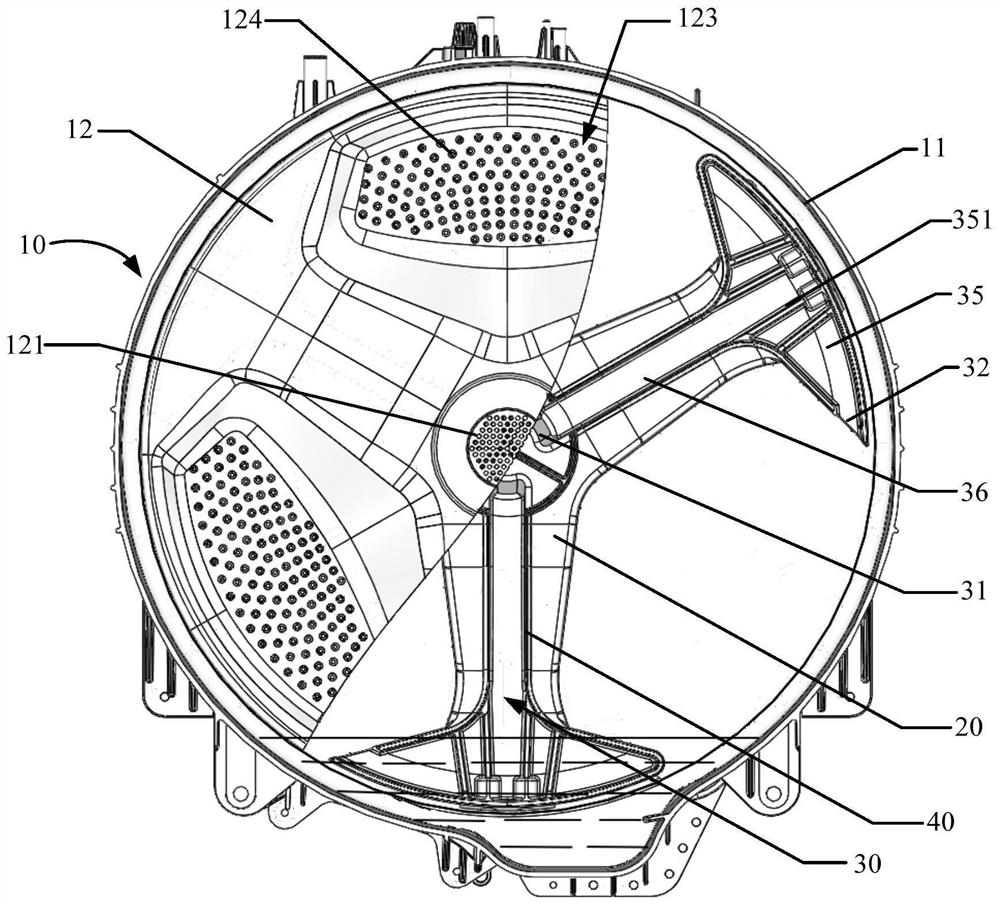
[0066] Such as figure 2 and Figure 7 As shown, in addition to the features of the above embodiments, it is further defined that: the flow channel 30 includes an expansion cavity 31 , the expansion cavity 31 is arranged corresponding to the water outlet 121 and communicated with the water outlet 121 , and the expansion cavity 31 communicates with the water inlet 32 ​​. In this way, the support frame 20 and the rear cover 12 can form a flow channel structure with more sufficient space, thereby improving the water guiding efficiency of the flow channel 30 and further improving the spraying effect.

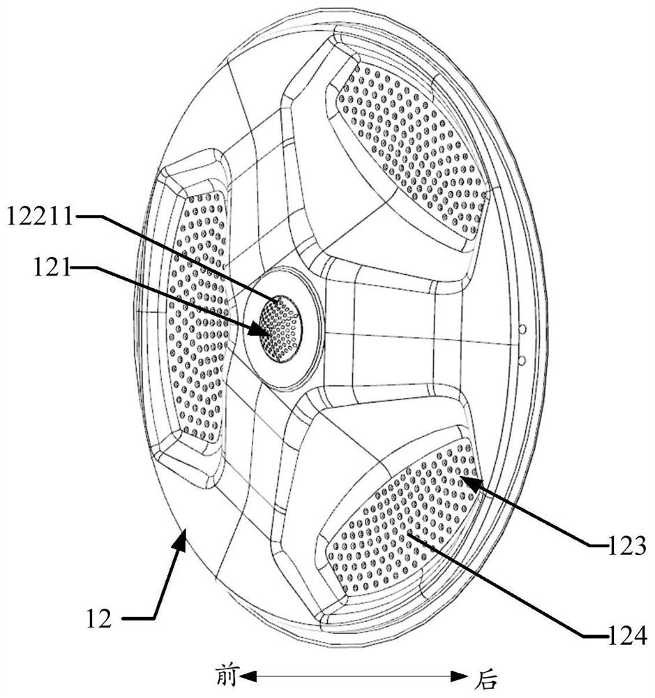
[0067] In detail, such as Figure 7 As shown, an expansion area 122 is formed on the back cover 12, and the expansion area 122 is surrounded by the support frame 20 to define the expansion cavity 31. The expansion area 122 includes a water outlet area 1221 and a sealing area 1222 arranged along the outer periphery of the water outlet area 1221. The water outlet area 1221 is provid...

Embodiment 2

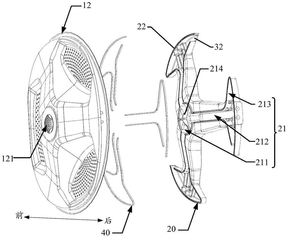
[0070] Such as Figure 5 and Figure 7 As shown, in addition to the features of the above embodiments, it is further defined that: the expansion area 122 includes a boss wall 1223, and the boss wall 1223 includes a top wall 12231 and a side wall 12232, and the top wall 12231 is provided with a water outlet 121, as Figure 4 As shown, the support frame 20 is provided with an expansion cavity 211 and ribs 214 arranged along the opening of the expansion cavity 211, and the top wall 12231 is arranged opposite to the opening of the expansion cavity 211 and blocks the opening of the expansion cavity 211. The rib 214 is inserted into the space enclosed by the side wall 12232 .

[0071] For example, the convex platform wall 1223 and the expansion concave cavity 211 form a convex and concave expansion cavity 31, which further increases the capacity of the expansion cavity 31 to ensure the spray water output, thereby increasing the spray volume accordingly, and the convex ribs 214 are ...

Embodiment 3

[0073] Such as Figure 7 As shown, in addition to the features of any of the above-mentioned embodiments, it is further defined that: the expansion chamber 31 is provided with one or more water outlet retaining ribs 33, and one or more water outlet retaining ribs 33 will expand the space in the chamber 31 Divided into a plurality of water outlet chambers 34 , the flow channel 30 is provided with a plurality of water inlets 32 , and the plurality of water inlets 32 communicate with the plurality of water outlet chambers 34 correspondingly.

[0074]For example, the water outlet retaining rib 33 is set to divide the space in the expansion cavity 31 into a plurality of water outlet chambers 34 along the circumferential direction, and the plurality of water inlets 32 communicate with the plurality of water outlet chambers 34 one by one, so that each water inlet 32 flows to the corresponding water outlet chamber 34, the water in each water outlet chamber 34 will not flow away from e...


PUM


Abstract

The invention provides a washing barrel assembly and a washing machine. The washing barrel assembly comprises a washing barrel and a supporting frame; the washing barrel is rotatably arranged and comprises a rotary drum and a rear cover; the rotary drum is connected with the rear cover; the rear cover is provided with a water outlet, and the water outlet is located at the central position of the rear cover; the supporting frame is connected with the rear cover; a flow channel is defined by the supporting frame and the rear cover; a water inlet is formed in the flow channel; the flow channel iscommunicated with the water inlet and the water outlet; and the supporting frame is configured to rotate and drive the washing barrel and the flow channel to rotate along with the supporting frame, so that the water inlet scoops water in the washing barrel and/or outside the washing barrel into the flow channel, and water in the flow channel is discharged into the washing barrel through the wateroutlet. According to the washing barrel assembly, the supporting frame is used for driving the washing barrel to rotate and driving water to spray clothes, so that the product composition is simplified, meanwhile, the power consumption cost is reduced, energy conservation and emission reduction are achieved; and the water outlet is formed in the rear cover, so that the water is directly sprayed into the washing barrel along the water outlet, spraying is more efficient, and the spraying visual effect is better.

Description

technical field [0001] The invention relates to the field of washing machines, in particular to a washing tub assembly and a washing machine. Background technique [0002] The drum washing machine lifts and beats the clothes through the rotation of the washing tub to achieve washing, so the drum washing machine has the advantages of less water and good water saving effect. Among them, in order to shorten the soaking time of the clothes in the existing drum washing machine; improve the utilization rate of detergent, washing uniformity, washing degree and rinsing efficiency, and save energy consumption, a water circulation spray device is usually installed outside the washing tub of the drum washing machine. Use external force such as a circulation pump to pump the water in the washing bucket out of the bucket through the circulation pipe and then enter the bucket through the spray device. In order to realize this process, the water pump needs to work continuously, which will ...

Claims


Application Information

Patent Timeline
IPC IPC(8): D06F37/12D06F39/08
CPCD06F37/12D06F39/083D06F39/08
Inventor 唐启庆
Owner WUXI LITTLE SWAN ELECTRIC CO LTD
Why Eureka
Try Eureka