Precision-adjustable composite sand control screen pipe
A sand control screen, high-precision technology, applied in wellbore/well components, production fluids, earth-moving drilling, etc., can solve problems such as large-scale prefabrication unfavorable for processing plants, difficulty in meeting use requirements, poor sealing at joints, etc., to avoid The effect of working pressure and working strength, good sealing, convenient installation and connection
- Summary
- Abstract
- Description
- Claims
- Application Information
AI Technical Summary
Problems solved by technology
Method used
Image

Examples
Embodiment 1
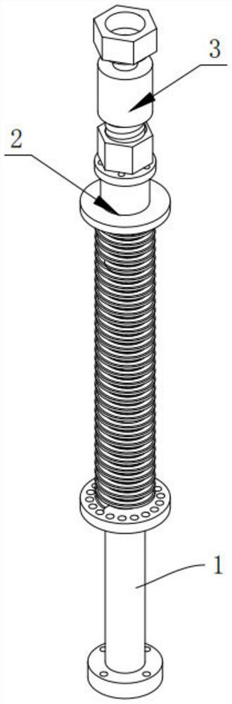
[0047] Such as figure 1 As shown, a precision-adjustable composite sand control screen according to an embodiment of the present invention includes a base pipe 1 , a precision-adjustable sand control mechanism 2 and a connecting mechanism 3 .
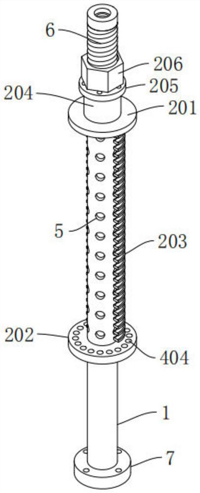
[0048] Among them, such as figure 1 , image 3 with Figure 9 As shown, both ends of the base pipe 1 are open structures, and a number of sieve holes 5 are uniformly opened on the wall of the middle part of the base pipe 1, and one end of the base pipe 1 is provided with a threaded part 6 outside, The other end of the base pipe 1 is welded with a connecting flange 7, and several mounting holes 10 are opened on the connecting flange 7 near its edge.
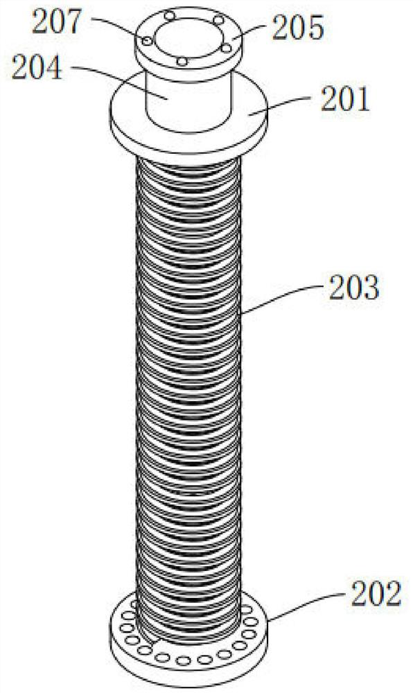
[0049] Among them, such as Figure 1-Figure 3 As shown, the precision adjustable sand control mechanism 2 includes a first annular connection seat 201, a second annular connection seat 202, a winding wire 203, a guide sleeve 204, an annular abutment seat 205 and an adjustment nut 206. T...
Embodiment 2
[0054] Such as Figure 6-Figure 7 As shown, the difference between this embodiment and Embodiment 1 is that the composite sand control screen with adjustable precision also includes a protection mechanism 4, and the protection mechanism 4 includes several circular through holes 404, several hollow round rods 403, an annular fixing seat 401 and several guide rods 402, several of the circular through holes 404 are opened on the second annular connecting seat 202, and several of the circular through holes 404 surround the second annular connecting seat The central axis of 202 is arranged at an equal angle in the circumferential direction, and several hollow round rods 403 are movably installed in the insides of several circular through holes 404, and several hollow round rods 403 are arranged parallel to the base pipe 1, And one end of the plurality of hollow round rods 403 is fixedly connected to a side of the first annular connecting seat 201 facing the second annular connectin...
Embodiment 3
[0057] Such as image 3 , Figure 7 with Figure 9 As shown, the difference between this embodiment and Embodiment 2 is that the first annular connecting seat 201, the second annular connecting seat 202, the annular fixing seat 401, the hollow round rod 403 and the The guide rods 402 are all made of stainless steel, the width of the gap between two adjacent hollow round rods 403 is 0.2-0.3 times the diameter of the sieve hole 5, and the installation holes 10 are at least four, and at least The four mounting holes 10 are circumferentially arranged at equal angles around the central axis of the connecting flange 7 .
[0058] By adopting the above technical scheme, the first annular connecting seat 201, the second annular connecting seat 202, the annular fixing seat 401, the hollow round rod 403 and the guide rod 402 are all made of stainless steel, so that the precision adjustable sand control mechanism 2 and the protective mechanism 4 has better load-bearing strength, less p...
PUM
 Abstract
Description
Claims
Application Information
 - R&D
- Intellectual Property
- Life Sciences
- Materials
- Tech Scout
- Unparalleled Data Quality
- Higher Quality Content
- 60% Fewer Hallucinations
Browse by: Latest US Patents, China's latest patents, Technical Efficacy Thesaurus, Application Domain, Technology Topic, Popular Technical Reports.
© 2025 PatSnap. All rights reserved.Legal|Privacy policy|Modern Slavery Act Transparency Statement|Sitemap|About US| Contact US: help@patsnap.com