
A test mold mechanism for rolling bearings and its application method

A technology for rolling bearings and testing molds, applied in mechanical bearing testing, measuring devices, instruments, etc., can solve problems affecting engineering use, bearing failure, complex costs of related equipment, etc.

Active Publication Date: 2021-11-30
佛山市喜舍机械设备有限公司
View PDF6 Cites 0 Cited by
  • Summary
  • Abstract
  • Description
  • Claims
  • Application Information

AI Technical Summary

Problems solved by technology

There are many types of rolling bearings, among which cylindrical roller bearings are widely used. The advantages of small radial size, simple structure, and large load-carrying capacity make roller bearings become important parts in the field of machinery industry. For standard rolling bearings in normal state In other words, the load and torque changes are relatively uniform, but due to installation errors, thermal deformation, geometric shape defects, etc., roller bearings generally operate under the conditions of deviation, skew, etc. Due to the radial clearance of the bearing and other reasons, the roller contact pair is in a deflected state, which will cause the bearing to fail prematurely, which will seriously affect the engineering use.
[0003] In fact, the current research on skewed roller bearings still exists in theoretical research, and there are not many related equipment for testing the load and torque conditions in the actual working process of skewed roller bearings, or the related equipment is relatively complicated and expensive , so there is an urgent need for a new type of test mold mechanism that can efficiently, reliably, stably and accurately skew roller bearings, in order to solve this problem

Method used

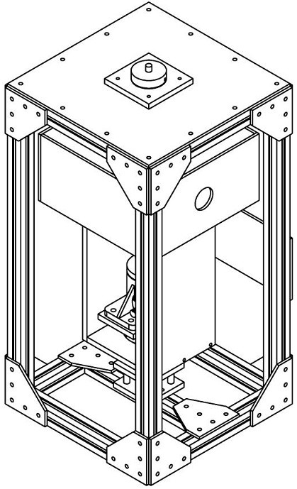
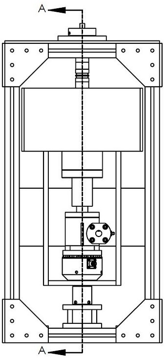
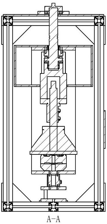

Image

  • A test mold mechanism for rolling bearings and its application method
  • A test mold mechanism for rolling bearings and its application method
  • A test mold mechanism for rolling bearings and its application method

Examples


Embodiment Construction

[0032] The present invention will be further described below in conjunction with specific examples.

[0033] The present invention will be described in detail below in conjunction with specific embodiments shown in the accompanying drawings. However, these embodiments do not limit the present invention, and any structural, method, or functional changes made by those skilled in the art according to these embodiments are included in the protection scope of the present invention. The application principle of the present invention will be further described below in conjunction with the accompanying drawings and specific embodiments.

[0034] The rolling bearing test mold mechanism of the present invention is used to test the magnitude of load and torque, and the measured values ​​can be used as a reference for the working state of the skewed roller bearing.

[0035] For the testing mold mechanism of the rolling bearing of the present invention, it comprises shell assembly 1, and ...


PUM


Abstract

A test mold mechanism for skewed rolling bearings is disclosed. The test mold mechanism includes a shell assembly, a frame assembly is arranged inside the shell assembly, the frame assembly includes an upper plate and a lower plate, and an action assembly is assembled on the frame assembly. The component integrates the main test area, the action component is assembled on the load sleeve, the load sleeve is assembled with the linear drive device, the weight sensor is installed under the linear drive device, and the torque sensor is installed under the weight sensor, and the linear drive device produces linear motion The action or tendency of the whole frame assembly produces an action or tendency along a straight line, so that the upper or lower plate of the frame assembly generates an impact load force, and then the weight sensor is measured, and the rotation or rotation tendency of the frame assembly is also The torque sensor is used for measurement, and the test mold mechanism has the characteristics of efficient, reliable, stable and precise operation.

Description

technical field [0001] The invention relates to the field of jig devices, more specifically, to a testing mold mechanism for rolling bearings and a method for using the same. Background technique [0002] As we all know, bearing is a very important component in the field of engineering equipment. Its main function is to support the mechanical rotating body, reduce the friction coefficient during its movement, and ensure its rotation accuracy. There are many types of rolling bearings, among which cylindrical roller bearings are widely used. The advantages of small radial size, simple structure, and large load-carrying capacity make roller bearings become important parts in the field of machinery industry. For standard rolling bearings in normal state In other words, its load and torque changes are relatively uniform, but due to installation errors, thermal deformation, geometric shape defects, etc., roller bearings generally operate under conditions such as deviation and skew...

Claims


Application Information

Patent Timeline
Patent Type & Authority Patents(China)
IPC IPC(8): G01M13/04G01D21/02
CPCG01D21/02G01M13/04
Inventor 孟令城
Owner 佛山市喜舍机械设备有限公司
Learn More