MT U-shaped magnetizer device

A magnetizer, U-shaped technology, applied in the direction of magnetic objects, material magnetic variables, electrical components, etc., can solve the problems of high labor intensity and low efficiency, and achieve the effect of easy flaw detection

Pending Publication Date: 2021-02-09
江苏梁宸科技有限公司
View PDF0 Cites 0 Cited by
  • Summary
  • Abstract
  • Description
  • Claims
  • Application Information

AI Technical Summary

Problems solved by technology

[0003] The operation of magnetic particle flaw detection: cleaning, spraying, rotating, magnetizing, observing, evaluating, demagnetizing, cleaning, painting, etc. At present, the longitudinal magnetization of domestic flaw detection equipment is magnetized by longitudinal coil or cable winding method within φ350. The general magnetization range is the diameter of the coil, and the direction of the magnetic field is generally perpendicular to the cross-section of the coil. For the end face of the inner hole, sharp corner, around the hole, sudden change in section, step and edge of the board wall, or the outer surface of the special-shaped part, the direction changes, the general traditional Coil flaw detection is segmented flaw detection, especially when L / D<2, the parts need to be connected in series for flaw detection, which is labor-intensive and low in efficiency. At the same time, when testing forgings with strict requirements, it is required to detect deep defects hidden under the skin. Therefore, three-phase full-wave rectifier detection is used. The general longitudinal (or circumferential, longitudinal AC demagnetization) demagnetization method cannot meet the standard demagnetization, so it cannot meet the normal work requirements.

Method used


Image

  • MT U-shaped magnetizer device

Examples


Embodiment Construction

[0015] In order to make the objectives, technical solutions and advantages of the present invention clearer, the present invention will be described in further detail below in conjunction with the accompanying drawings and embodiments. It should be understood that the specific embodiments described here are only used to explain the present invention and are not intended to limit the invention.

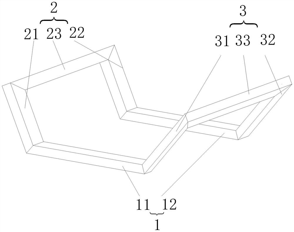
[0016] see figure 1 , The present invention provides an MT "U" type magnetizer device, which includes a first flaw detection assembly 1 , a second flaw detection assembly 2 and a third flaw detection assembly 3 .

[0017] The first flaw detection component 1 includes two first red copper row groups 11 and the second red copper row group 12 arranged parallel to each other, and the second flaw detection component 2 and the third flaw detection component 3 are arranged symmetrically and obliquely on the first red copper row group 11 and the second red copper row group 12 respectively. Th...


PUM

PropertyMeasurementUnit
thicknessaaaaaaaaaa
lengthaaaaaaaaaa
lengthaaaaaaaaaa

Abstract

The invention is suitable for the technical field of magnetization flaw detection, and provides an MT U-shaped magnetizer device which is characterized in that a first flaw detection assembly comprises a first red copper bar set and a second red copper bar set which are arranged in parallel, a second flaw detection assembly and a third flaw detection assembly are symmetrically and obliquely arranged at the two ends of the first red copper bar set and the two ends of the second red copper bar set correspondingly and fixedly connected with the first red copper bar set and the second red copper bar set, and the cross sections of the first flaw detection assembly, the second flaw detection assembly and the third flaw detection assembly are in a U shape. By adopting the longitudinal U-shaped magnetizer device, three-dimensional magnetic field magnetization in the X direction, the Y direction and the Z direction can be achieved, and meanwhile, polarity-changing attenuation demagnetization can be tangentially carried out on the inner hole end face, the sharp corner, the periphery of a hole, the abrupt change part of the cross section, steps, the edge of a plate wall and magnetic fields deep in different directions of the special-shaped part through the longitudinal U-shaped coil.

Description

technical field [0001] The invention belongs to the technical field of magnetization flaw detection, in particular to an MT "U" type magnetizer device. Background technique [0002] Magnetic particle inspection is to use its discontinuity near the surface defect of steel parts to generate leakage magnetic field on the surface of the workpiece to attract magnetic powder to form magnetic particle accumulation-magnetic marks at the defect, observe, evaluate and analyze under appropriate lighting conditions to achieve non-destructive testing. Purpose. [0003] The operation of magnetic particle flaw detection: cleaning, spraying, rotating, magnetizing, observing, evaluating, demagnetizing, cleaning, painting, etc. At present, the longitudinal magnetization of domestic flaw detection equipment is magnetized by longitudinal coil or cable winding method within φ350. The general magnetization range is the diameter of the coil, and the direction of the magnetic field is generally pe...

Claims


Application Information

Patent Timeline
Patent Type & Authority Applications(China)
IPC IPC(8): G01N27/84H01F13/00
CPCG01N27/84H01F13/003
Inventor 倪卫华李强倪建钰祁白玉
Owner 江苏梁宸科技有限公司
Why Eureka
Try Eureka