Lighting system and projection device

A lighting system and projection device technology, applied in the field of optical systems, can solve problems such as large volume, and achieve the effect of simple optical path design and good color performance

Inactive Publication Date: 2021-02-09
CORETRONIC
View PDF7 Cites 0 Cited by
  • Summary
  • Abstract
  • Description
  • Claims
  • Application Information

AI Technical Summary

Problems solved by technology

[0004] However, the optical path design of the above-mentioned projection device requires the existence of both a short-wavelength blue light source for exciting the phosphor and a long-wavelength blue light source for providing blue light, and the long-wavelength blue light does not need to pass through the wavelength conversion module, so the short-wavelength blue light The light source and the long-wavelength blue light source will be located on different optical paths, so that the overall device needs a larger volume to provide the space required for the optical path design
[0005] In addition, it is known that there is another way to obtain red light or improve the performance of red light by adding an auxiliary light source. The laser is combined, and the blue light source is arranged in a conjugate arrangement relative to the color separation element, so it will also be located on a different optical path from the blue light source, and the overall device will still require a larger volume to provide the optical path space required for design

Method used


Image

  • Lighting system and projection device
  • Lighting system and projection device
  • Lighting system and projection device

Examples


Embodiment Construction

[0055] The foregoing and other technical contents, features and effects of the present invention will be clearly presented in the following detailed description of a preferred embodiment with reference to the accompanying drawings. The directional terms mentioned in the following embodiments, such as: up, down, left, right, front or back, etc., are only referring to the directions of the drawings. Accordingly, the directional terms are used to illustrate and not to limit the invention.

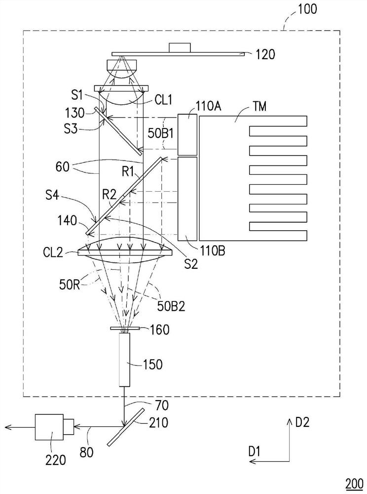
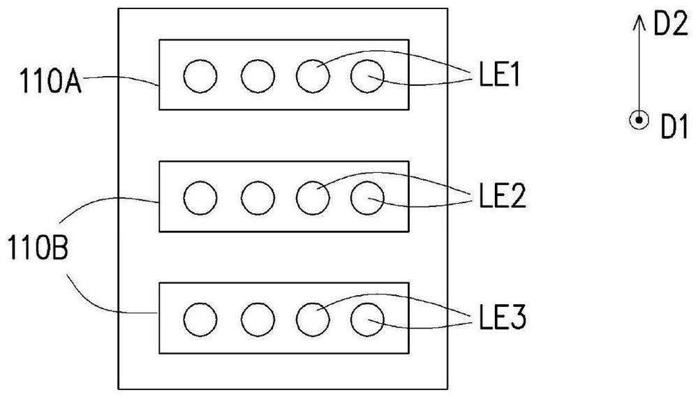
[0056] Figure 1A It is a schematic structural diagram of a projection device according to an embodiment of the present invention. Figure 1B yes Figure 1A The top view of the configuration relationship between the first laser light source module and the second laser light source module. Please refer to Figure 1A, the projection device 200 includes an illumination system 100 , a light valve 210 and a projection lens 220 . The lighting system 100 is used to provide the lighting beam 70 . T...


PUM


Abstract

The invention provides a lighting system and a projection device. The lighting system comprises a first laser light source module for providing a first laser beam, a second laser light source module for providing a second laser beam and a third laser beam, a wavelength conversion module, a first light splitting unit and a second light splitting unit. The first laser beam, the second laser beam andthe third laser beam are emitted from the first laser light source module and the second laser light source module along a first direction respectively. The wavelength conversion module converts thefirst laser beam into an excited beam. The first light splitting unit and the second light splitting unit are substantially non-parallel, and one of the first light splitting unit and the second lightsplitting unit forms an illumination beam by the excited beam, the second laser beam and the third laser beam. The lighting system and the projection device have the advantages of small size and concise light path design.

Description

technical field [0001] The present invention relates to an optical system and an optical device including the above optical system, and in particular to an illumination system and a projection device. Background technique [0002] Recently, projection devices based on solid-state light sources such as light-emitting diodes (LEDs) and laser diodes (laser diodes) gradually occupy a place in the market. Generally speaking, the excitation light of these solid-state light sources will be converted by the wavelength conversion material on the wavelength conversion module in the projection device to generate converted light of different colors. And in order to meet the requirement of color performance, a filter module is placed on the rear optical path of the projection device, and the converted light on the wavelength conversion module filters out predetermined color light after passing through the filter module. These colored lights are modulated by the light valve to project th...

Claims


Application Information

Patent Timeline
Patent Type & Authority Applications(China)
IPC IPC(8): G03B21/20
CPCG03B21/2013G03B21/204G03B21/16G03B21/2033G03B33/12
Inventor 蔡志贤史梅君
Owner CORETRONIC
Why Eureka
Try Eureka