Power supply system power equipment life cycle management method and system

A life cycle and power equipment technology, applied in the field of power system power supply equipment management, can solve problems such as the inability to conduct continuous comparative analysis and accurate evaluation, the difference in the cumulative inspection frequency of power equipment, and increase the risk of power equipment operation, etc., to achieve outstanding substantive features , Reliable design principle and simple structure

Pending Publication Date: 2021-02-09
STATE GRID SHANDONG ELECTRIC POWER CO BOXING POWER SUPPLY CO
View PDF5 Cites 6 Cited by
  • Summary
  • Abstract
  • Description
  • Claims
  • Application Information

AI Technical Summary

Problems solved by technology

[0002] The power equipment of the power supply system is generally supervised and managed in the way of regular inspection, and the scope of maintenance is usually carried out in accordance with the sampling ratio required by relevant standards. There are many problems in this supervision and management mode, such as random inspection with blindness and low level of informationization. It is impossible to conduct continuous comparative analysis and accurate evaluation; there are obvious differences in the cumulative inspection frequency of various electrical equipment, over-inspection, over-repair and under-inspection, and missed inspections are common. The failure of equipment will virtually increase the operation risk of power equipment

Method used


Image

  • Power supply system power equipment life cycle management method and system
  • Power supply system power equipment life cycle management method and system

Examples


Embodiment Construction

[0069] In order to enable those skilled in the art to better understand the technical solutions in the present invention, the technical solutions in the embodiments of the present invention will be clearly and completely described below in conjunction with the drawings in the embodiments of the present invention. Obviously, the described The embodiments are only some of the embodiments of the present invention, not all of them. Based on the embodiments of the present invention, all other embodiments obtained by persons of ordinary skill in the art without making creative efforts shall fall within the protection scope of the present invention. Key terms appearing in the present invention are explained below.

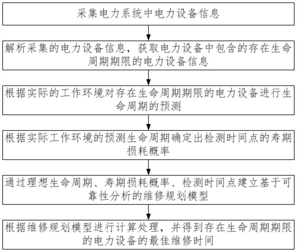
[0070] Such as figure 1 As shown, the embodiment of the present invention provides a power supply system power equipment life cycle management method, including the following steps:

[0071] S1: Collect power equipment information in the power system; in this step, the ...


PUM


Abstract

The invention provides a life cycle management method and system for power equipment of a power supply system. The method comprises the following steps: acquiring power equipment information in the power system; analyzing the collected power equipment information, and obtaining the power equipment information with the life cycle deadline contained in the power equipment; predicting the life cycleof the power equipment with the life cycle period according to the actual working environment; determining the lifetime loss probability of the detection time point according to the predicted life cycle of the actual working environment; establishing a maintenance planning model based on reliability analysis through the ideal life cycle, the lifetime loss probability and the detection time point;and performing calculation processing according to the maintenance planning model, and obtaining the optimal maintenance time of the power equipment with the life cycle deadline. Therefore, the maintenance is purposeful, the informatization level is high, the situation that the service life expires is properly handled, and the operation risk of power equipment is reduced.

Description

technical field [0001] The invention relates to the technical field of management of power supply equipment in a power system, in particular to a method and system for lifecycle management of power equipment in a power supply system. Background technique [0002] The power equipment of the power supply system is generally supervised and managed in the way of regular inspection, and the scope of maintenance is usually carried out in accordance with the sampling ratio required by relevant standards. There are many problems in this supervision and management mode, such as random inspection with blindness and low level of informationization. It is impossible to conduct continuous comparative analysis and accurate evaluation; there are obvious differences in the cumulative inspection frequency of various electrical equipment, over-inspection, over-repair and under-inspection, and missed inspections are common. The failure of equipment will virtually increase the operation risk of...

Claims


Application Information

Patent Timeline
Patent Type & Authority Applications(China)
IPC IPC(8): G06Q50/06G06Q10/04G06Q10/00G06N3/04G06N3/00G06F30/27G06F30/23H02B3/00G06F119/02G06F119/04
CPCG06Q50/06G06Q10/04H02B3/00G06Q10/20G06F30/27G06N3/006G06F30/23G06F2119/02G06F2119/04G06N3/045
Inventor 邢观明曹金京杨军王云伟冀博相青海韩海涛杨云涛焦裕剑张鲁东
Owner STATE GRID SHANDONG ELECTRIC POWER CO BOXING POWER SUPPLY CO
Why Eureka
Try Eureka