Eureka AIR delivers breakthrough ideas for toughest innovation challenges, trusted by R&D personnel around the world.

Photovoltaic power station reactive power compensation device

A photovoltaic power station and compensation device technology, which is applied in reactive power compensation, photovoltaic power generation, substation/distribution device housing, etc., can solve problems such as economic loss, poor dustproof ability, weak earthquake resistance, etc., and achieve capacity waste and cost increase , easy to move and carry, to ensure the effect of service life

Pending Publication Date: 2021-02-09
湖南安华源电力科技有限公司
View PDF0 Cites 1 Cited by
  • Summary
  • Abstract
  • Description
  • Claims
  • Application Information

AI Technical Summary

Problems solved by technology

Therefore, the reactive power compensation device is in an indispensable and very important position in the power supply system. Reasonable selection of the compensation device can minimize the loss of the network and improve the quality of the power grid. On the contrary, if you choose or use Improper power supply system, voltage fluctuation, harmonic increase and many other factors may be caused. The traditional reactive power compensator has a single structure, poor heat dissipation, weak earthquake resistance, and poor dustproof ability. Directly lead to damage to the internal components of the compensator, resulting in economic losses

Method used


Image

  • Photovoltaic power station reactive power compensation device
  • Photovoltaic power station reactive power compensation device
  • Photovoltaic power station reactive power compensation device

Examples


Embodiment Construction

[0027] In order to enable those skilled in the art to better understand the present invention, the technical solution of the present invention will be further described below in conjunction with the accompanying drawings and embodiments.

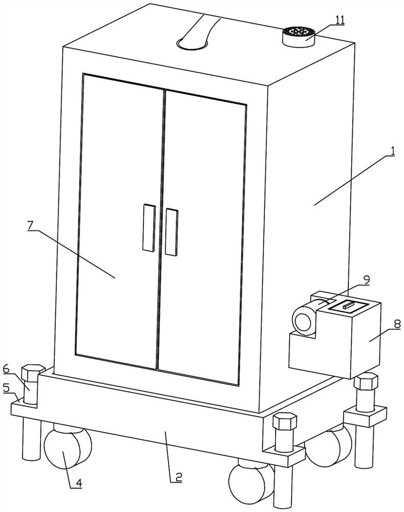
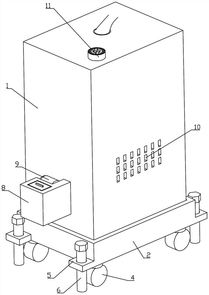
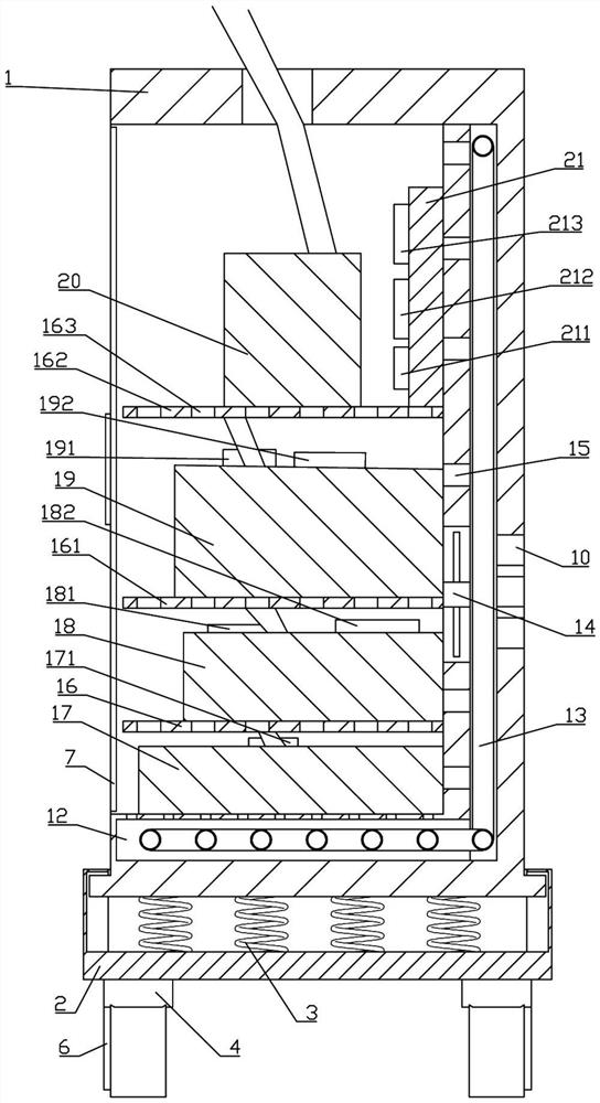
[0028] Such as figure 1 , figure 2 , image 3 As shown, the photovoltaic power station reactive power compensation device of the present invention includes a device main body 1, a shock absorber 2 is slidingly matched with the bottom of the device body 1, a spring group 3 is installed between the shock absorber 2 and the device main body 1, and the shock absorber 2 Four universal wheels 4 are connected to the bottom, four fixed blocks 5 are integrally connected to the side of the shock absorbing box 2, and the fixed blocks 5 are threadedly connected with top piles 6. Coolant tank 8, pump 9 is installed in coolant tank 8, cooling holes 10 are provided on the back of device main body 1, tuyere 11 is provided on the top of device main body 1...


PUM


Abstract

The invention discloses a photovoltaic power station reactive power compensation device which comprises a device body, a damping box is arranged at the bottom of the device body in a sliding fit mode,a spring set is installed on the damping box, the damping box is connected with universal wheels, a fixing block and a top pile, and the device body is provided with an opening and closing door, a cooling liquid box, a pump, heat dissipation holes, an air opening and a cavity. A cooling liquid pipe is installed in the cavity, the cavity is provided with a fan and a through hole, a first installation plate, a second installation plate and a third installation plate are integrally connected into the device body, and the first installation plate, the second installation plate and the third installation plate are each provided with a plurality of air holes. A photovoltaic cell, a first knife fuse switch, a photovoltaic inverter, a first acquisition module, a first judgment module, an adjuster, a second knife fuse switch, a first switching module, an electric reactor, a side mounting plate, a second acquisition module, a second judgment module and a second switching module are placed amongthe first installation plate, the second installation plate and the third installation plate.

Description

technical field [0001] The invention belongs to the field of photovoltaic power plants, and in particular relates to a reactive power compensation device for photovoltaic power plants. Background technique [0002] With the development and progress of science and technology, people's requirements for things have changed from the old thinking that can be used to become quite delicate and demanding. Only the idea of ​​continuous improvement or innovation will produce new forms to increase the added value of products. , in order to survive under the test of fierce market competition. [0003] The loads of photovoltaic power station projects are mostly inductive loads. A large number of inductive loads not only cause the system power factor to be too low, reduce production efficiency, and increase the power expenditure of the enterprise, but also cause voltage fluctuations in the grid, which will affect the safe operation of the load equipment and bring unnecessary economic los...

Claims


Application Information

Patent Timeline
Patent Type & Authority Applications(China)
IPC IPC(8): H02J3/38H02J3/18H02B1/54H02B1/56H02B1/52H02B1/28
CPCH02B1/28H02B1/52H02B1/54H02B1/56H02J3/18H02J3/38H02J2300/24Y02E10/56Y02E40/30
Inventor 李宁良周世大肖慧明
Owner 湖南安华源电力科技有限公司
Why Eureka
Eureka Blog
Learn More