
Magnet polarity detection equipment

A polarity detection and magnet technology, applied in the field of detection equipment, can solve problems such as high labor intensity, poor operability, and misjudgment, and achieve the effect of high labor intensity, wide application fields, and accurate detection results

Active Publication Date: 2021-02-12
GEER TECH CO LTD
View PDF18 Cites 4 Cited by
  • Summary
  • Abstract
  • Description
  • Claims
  • Application Information

AI Technical Summary

Problems solved by technology

This manual detection method is not only labor-intensive and inefficient, but also has poor operability, and it is prone to misjudgment caused by permanent magnets. Therefore, it cannot meet the requirements of the existing process and production rhythm.

Method used


Image

  • Magnet polarity detection equipment
  • Magnet polarity detection equipment
  • Magnet polarity detection equipment

Examples


Embodiment Construction

[0027] The specific implementation manners of the present invention will be further described in detail below in conjunction with the accompanying drawings.

[0028] It should be noted that, in the description of the present invention, the terms "inner", "outer", "upper", "lower", "top", "bottom" and other terms indicating direction or positional relationship are based on the terms shown in the accompanying drawings. Orientation or positional relationship, which is only for convenience of description, and does not indicate or imply that the device or element must have a specific orientation, be constructed and operated in a specific orientation, and thus should not be construed as a limitation of the present invention.

[0029] In addition, it should be noted that in the description of the present invention, unless otherwise specified and limited, the terms "installation" and "connection" should be interpreted in a broad sense. For example, it can be a fixed connection, a deta...


PUM


Abstract

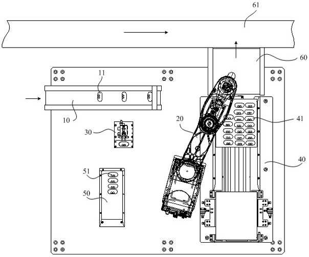
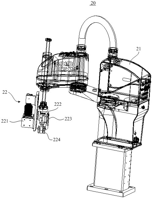
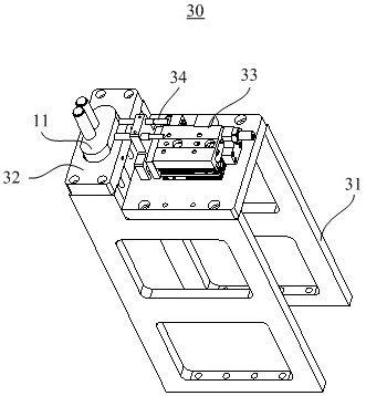
The invention discloses magnet polarity detection equipment. The equipment comprises a feeding platform, a Hall detection platform, a stock bin platform, a manipulator and a control system; a Hall sensor for detecting the magnet polarity is arranged on the Hall detection platform; the manipulator is used for grabbing a to-be-detected product from the feeding platform, placing the to-be-detected product on the Hall detection platform, and grabbing the qualified product and placing the same on the stock bin platform after the to-be-detected product placed on the Hall detection platform is detected to be qualified; and the control system is used for controlling the manipulator to act, receiving an induction signal output by the Hall sensor after detection, judging the magnetic pole mounting direction of a magnet in the to-be-detected product according to the induction signal, and determining the to-be-detected product with the correct mounting direction as the qualified product. Accordingto the magnet polarity detection equipment, the polarity of the magnet arranged in the to-be-detected product can be automatically detected, and whether the magnetic pole of the magnet is reversely mounted in the to-be-detected product or not can be automatically recognized.

Description

technical field [0001] The invention belongs to the technical field of detection equipment, and in particular relates to a special equipment for detecting the polarity of a magnet. Background technique [0002] At present, many electronic products on the market often implement certain functions by configuring magnets. The charging case that is used to charge the wireless earphones and also to store the earphones is used as an example for illustration. In this type of earphone charging box, there are often multiple built-in magnets for different functions. For example, some magnets are used to attract the cover of the charging box; some magnets are used to absorb and lock the earphone after the earphone is inserted into the charging box, so as to ensure that the charging contacts on the earphone can be connected to the charging box. The charging electrodes are kept in effective contact, so that the charging process can be carried out smoothly. [0003] During the productio...

Claims


Application Information

Patent Timeline
Patent Type & Authority Applications(China)
IPC IPC(8): B07C5/02B07C5/344B07C5/36G01R33/12
CPCB07C5/02B07C5/344B07C5/362G01R33/12B07C2301/0008B07C2501/0063
Inventor 邱阔刘元江周忠厚丁浩浩刘骇浪刘剑程思凯
Owner GEER TECH CO LTD
Learn More